![]()
![]()
![]()
![]()

- V1.0: Pre-release
- V1.1: First release
- V1.2: New options
- -x++..-z-- are similar to -x+..-z-, but use an offset parameter to be able to use any plane in main directions, not just origin planes.
- -i inverts direction of split. No need to invert winding of elements in splitter file. This is active also for main plane splits, so -i -x+ is the same as -x-
- -d0 options deletes nothing. This allows to snap elements of a file to splitter plane(s). Warning: splitter planes are infinite, so snapping may occur in areas far form the area you want to modify!
- The input file may contain any LDraw type. Primitives and subfiles are ignored unless SymSplitter is told to inline them.
- Prepare the splitter file, defining splitting planes as triangles or quads. Alternately the splitting planes can be defined by command lines options (only for main x/y/z planes)
- Launch a command prompt
- Type the command line: SymSplitter [options] Infile, [SplitterFile] Outfile. SymSplitter will create Outfile, containing the elements separated and/or cut by the planes. Note that if file Outfile exists it will be overwritten without warning.
- Input files are parsed, and their content is stored into arrays. If splitting planes are only defined by command line options, a splitting array is created from them.
- If the user selected subfile inlining (-s option), the main file array is scanned and all subfiles/primitives that are found in defined LDraw path (-l option) are inlined at the end of the array to be split. This inlining is done in a BFC compliant way.
- For each plane defined in splitter file (either as a
triangle or a quad), all elements of input file are checked
and sorted in 4 categories:
- Element is completely on the "keep it" side of plane (this side is the BFC-red side for a CCW certified file).
- Element is completely on the "discard it" side. These elements are deleted.
- Element lies entirely in the splitting plane
- Element extends on both sides of plane.
Option -i (new in version 1.2) swaps "keep it" and "discard it" sides.
- Sorting special cases:
- Only the line part of conditional lines determine the category. Control point may be on any side of it.
- Primitives and subparts are sorted only according to their origin. This often works well... but not always! Watch out...
- Stud primitives that may contain a LEGO logo (stud.dat, stud2.dat, stug*.dat) are always considered to be in the middle section. This avoids to include them in side subfiles that are generally mirrored.
- During this sorting process, all vertices whose distance to the splitting plane is lower than defined precision (-p) are snapped onto that plane. While small adjustments are generally useful and harmless, larger ones (higher values of -p) may result in warped quads, distorted shapes or unmatched conditional lines. This snapping may be disabled by specifying a 0 value for -p.
- If -c is specified, elements are colored depending on
their category:
- Elements entirely in the splitting plane are colored in blue (primitives, subfiles, triangles and quads) or light blue (lines, conditional lines)
- Elements extending across splitting plane are colored in yellow (primitives, subfiles, triangles and quads) or red (lines, conditional lines)
- Additional elements are deleted according to other command
line options:
- -di deletes all elements that lie entirely in the splitting plane
- -da deletes all elements that extend across the splitting plane
- -dn deletes all elements that are not in or across the splitting plane
- -d0 deletes nothing. This option is useful if you only want to snap element vertices to splitter plane (new in version 1.2)
- If -v is specified, elements across splitting plane are checked to be self-symmetrical against that plane (no test is performed for primitives/subfiles). Elements that are not self symmetrical are flagged in pink (surfaces) and light green (lines, conditional lines). Note that -v takes precedence over -c.
- if "cut across" (-ca) is specified, elements are cut by the splitting plane, and portions on the wrong side are deleted.
- Output file is written.
|
SymSplitter:
split LDraw files along their symmetry planes (and more!)
SymSplitter is the tool of choice when you want to exploit symmetries in a LDraw file to reduce its size. You may use it to separate left/right/middle parts, cut parts by planes, and adjust vertices coordinates to make sure they lie precisely in plane.
It is a simple console application, source code is provided below to anyone willing to integrate it in a more palatable user interface. You may also use Michael Heidemann LETGUI front-end (highly recommended!).
Download
SymSplitter package, including program for Windows, documentation, source files (Visual C++ 6.0), sample files.
History
Usage
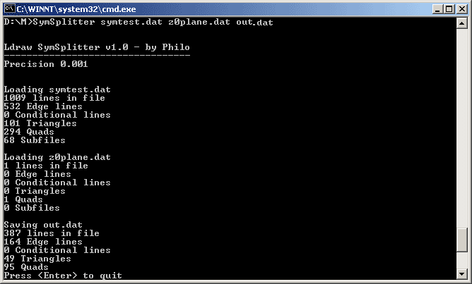
Here is a screen shot of a sample run:
How SymSplitter works
Sorting out
|
|
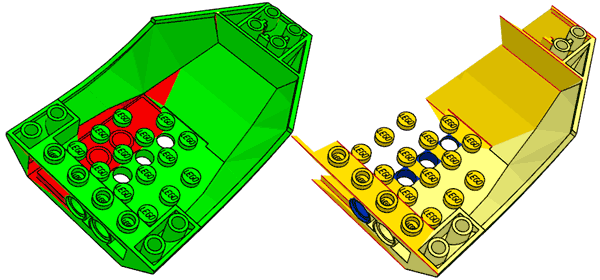
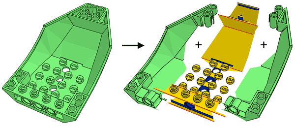
This is the simplest purpose of SymSplitter: separate a symmetrical part into its central area that will be included in the main part file, and one side section that will be subfiled and mirrored to form both sides. The example comes from LEGO Universe Team data of part 47406. After a lot of primitive substitution and adjustment of quads/triangles to match them, I had the following file (left) with middle and one side completed. Simple use of SymSplitter with coloring shows (right) what will become center section and side subpart. We shall separate by the plane z=0 and keep z<0 data. Since this separation occurs in one of the main cartesian planes, there is no need to provide a splitting file and we'll use -z- option (meaning split by z=0 plane, keep z<0. -z+ would be used to keep z>0, -x- or -y+ are similar for x=0 and z=0 planes). Command line: SymSplitter -z- -c 47406-ssp.dat 47406-col.dat |
|
|
|
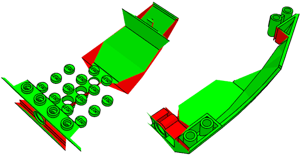
We may now do the separation itself. Using -dn parameter deletes everything that is not in the middle section, while -di -da leaves only the side. Note that though they are not centered, studs are included in middle section to avoid stud mirroring issues. Command line: SymSplitter -z- -dn 47406-ssp.dat 47406-mid.dat SymSplitter -z- -di -da 47406-ssp.dat 47406-side.dat |
|
|
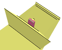
We now check wether the middle area is self-symmetrical, using -v option. It appears that a small area is not, showing pink and bright green. After closer analysis it turns out that it is caused by minor rounding errors. Increase precision threshold to 0.01 removes the warning. Default value for precision is 0.001. Note that -v has its limitations: primitives or subfiles are not verified (you may try to inline them for the check using -s option), and it is possible that quads/triangles forms a self-symmetrical shape while each component is not. Command line: SymSplitter -z- -v 47406-mid.dat 47406-ver.dat
SymSplitter -z- -v -p 0.01 47406-mid.dat 47406-vok.dat |
Trimming
|
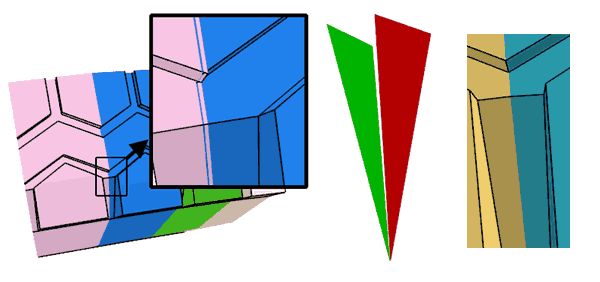
The trimming usage of SymSplitter was the first I tested "in real life". Tire part ref. 32003 had been on Parts Tracker for a long time, the subpart was created a tad too large and the segments overlapped each other, preventing proper use of conditional lines between subparts. A splitter file was created with two triangles defining planes with an angle of 10° (the tire has 36 segments). Note the orientation of the planes, "red" faces inside the V shape. It was applied to the 32003a subfile with increasing precision threshold values. For p = 0.1 the elements of the subpart properly snapped to the splitting planes - the issue was corrected, without actually cutting anything. Important warning: snapping feature can produce non-planar quads, or even gaps if initial parts contains T-junctions. Check carefully! Command line: SymSplitter -p 0.1 32003a.dat 32003sep.dat 32003aok.dat |
Mesh splitting
|
Meshes created with a 3D scanner, such as my NXT based one, or DAVID laserscanner, often need to be cut in half, or modified to get a true flat base plane. Intersector can do the job, but often tiny triangle remains because of vertices very close (but not on) the cutting plane. Using the plane snapping feature of SymSplitter with a rather high precision threshold can help (sometimes you don't need to cut anything at all!) The example above shows how to form a flat base plane under the frog mesh acquired with my NXT based scanner. As threshold is increased, more and more vertices get attracted onto the plane y=0. Yellow elements intersect the base plane. For p=0.3 you get a flat base, nothing crosses the plane. Of course p should remain low enough to prevent too much deformations. Command line: SymSplitter -c -y- -p 0.25 frog.dat frogp0.25.dat
SymSplitter -c -y- -p 0.3 frog.dat frogp0.3.dat
|
|
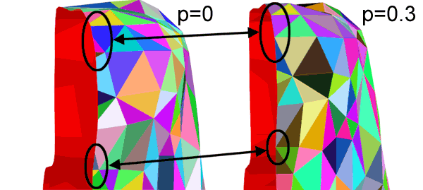
To split the frog you'll need to cut elements to get a clean result. Specifying a higher threshold gets rid of tiny triangles and reduces the number of cut elements. The example above shows the area near the frog head and the simplification as p is increased from 0 to 0.3. Command line: SymSplitter -ca -x+ -p 0 frog.dat frogxp0.dat
SymSplitter -ca -x+ -p 0.3 frog.dat frogxp0.3.dat
|
![]()

![]()
![]()
![]()
