![]()
![]()
![]()
![]()

![]()
![]()
![]()
![]()
![]()
![]()
![]()
![]()
![]()
![]()
![]()
|
Tutorial: Building shapes with Quad2Dat, Edger and Ytruder
...featuring guest stars: LDraw Design Pad and MLCad. Director of photography: LDView
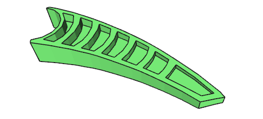
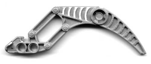
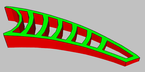
This tutorial describes how I created the finger of 50914 part, using several tools.
Download
This tutorial, (PDF), including all sample files.
|
The part is scanned or photographed File: 50914.jpg |
|
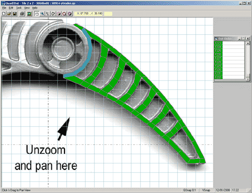
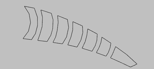
The image is imported in Quad2Dat, and scaled properly. The finger edge is covered with quads. Quad2Dat template is not used here, you can avoid displaying it (in menu View > Options, go to Display tab and uncheck "Template". Important tip: Quad2Dat has the bad habit of crashing when you save. So save often, using different names (since the crash occur when you save, you may get only a partial file and loose all your previous work). File: 50914-ytruder.qp |
|
Export your work as a LDraw file. Edit it (using either LDDesignPad or MLCad) to remove the template part. Translate the finger to the top at Y = -7 (Edit>Select>All, then click on the "Enter position rotation" icon, and type -7 in Y box) Using LDDesignPad, inline any primitive used (we'll later use Edger to find edges around the shape, and Edger does't process primitives). Note: for rounding errors it may be even better to "explode" primitives within Quad2Dat before exporting the .dat file. File: 50914-tip1.dat |
|
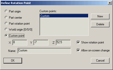
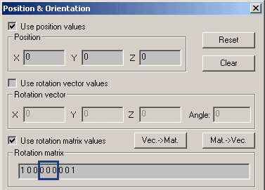
The tip of the part is thinner so we need to rotate it by a few degrees, using MLCad. First the rotation origin is set to the base of the finger (X=8, Y=-7, Z=52.5). |
|
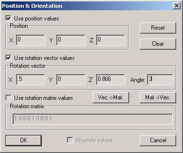
We then rotate the shape. Select it (Edit>Select>All), then click on the "Enter position rotation" icon. The dialog box shown on the left will open. We use the rotation around a vector. The rotation vector is chosen to be approximately perpendicular to the finger. A 3° angle gives a correct slope. Alternatively you could perform this rotation using regular X-Y-Z rotation by first aligning the finger with the X axis (a 30° rotation around Y), then rotate 3° around Z axis, then restore the orientation with a 30° rotation around Y in the opposite direction. File: 50914-tip2.dat |
|
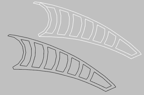
The next step is to draw an edge line around the shape. Edger is the tool of choice here (see how to setup Edger as an LDDP plugin). Run Edger on previous file, and open Edger-result.dat file in LDDP. Get rid of all conditional lines created by Edger, only the edge lines are useful here (though the surface is flat, rounding errors during the rotation operation leads Edger to generate conditional lines everywhere). File: 50914-tip3.dat Notice that there are unwanted lines around the ring primitive, once again caused by rounding errors (this could be avoided by exploding the primitive in Quad2Dat). We get rid of them using MLCad. First change all line colors from white (15) to edge color (24) to see something on the white background, then select and delete unwanted lines. File: 50914-tip4.dat |
|
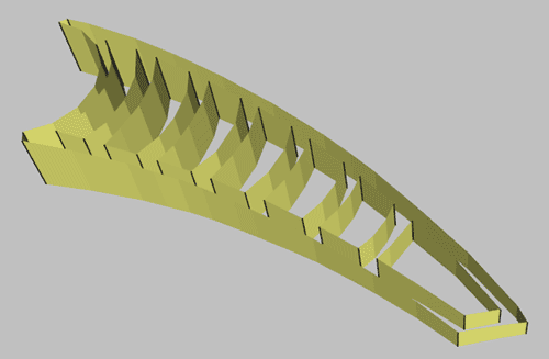
Ytruder is now needed to create the sides of the shape. Assuming you put a copy of Ytruder in your job folder containing all tutorial files, the command line is: Ytruder -s 0 50914-tip4.dat 50914-tip5.dat since we do an extrusion symmetrical across plane Y=0. Note that regular lines are correctly generated instead of conditional lines when there is a sharp bend in the shape. File: 50914-tip5.dat |
|
Using LDDP, we merge the top surface, side surface and top edge line in a single file. Be sure to insert comments between sections to later recognize them. It's time to have a look at facet orientation. Insert a "0 BFC CERTIFY CCW" statement and check with LDView using red/green BFC mode. We see that the side is backwards, in LDDP select all text lines in side surface section and reverse their winding (Tools > Reverse Winding). File: 50914-tip6.dat (before winding inversion) |
|
Still within LDDP, we now create bottom surface. Copy the top surface and top edge line sections. Edit the comments appropriately. Select the duplicated sections and mirror them (Tools > Mirror Lines on > Y Axis). Since mirroring a facet reverses its winding, select the bottom surface section and reverse its winding (Tools > Reverse Winding). File: 50914-tip7.dat |
|
We now need to create the middle sheet, and first the edges where it meets the ribs. In MLCad, open top edge line file (50914-tip4.dat) and remove all outside lines, keeping only those bordering middle cells. File: 50914-tip8.dat |
|
The middle sheet is flat, while the lines we have are leaning towards the tip. Using MLCad the lines are projected onto plane Y=0. Select everything (Edit>Select>All), then click on the "Enter position rotation" icon. Fill the dialog box as shown (all three Y coefficient of the rotation matrix are set to 0). The flattened lines are then translated to plane Y=-2, then duplicated to plane Y=2. File: 50914-tip9.dat |
|
Using LDDP, the middle lines are appended to the main file File: 50914-tip10.dat |
|
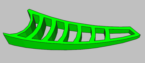
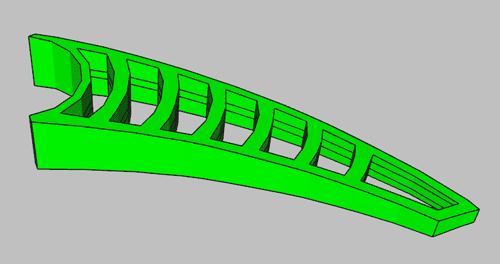
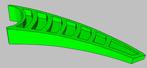
Finally, using MLCad we add two surfaces that covers all the middle cells. Since the part is not transparent, no attempt is done to follow the edges exactly, resulting in a minimum quads number. Should the exact surface be needed, we could draw it using Quad2Dat, rotate and flatten it the same way we did for the middle lines. File: 50914-tip11.dat |

|
![]()
![]()
![]()
![]()
![]()
![]()
![]()
![]()
![]()
![]()
![]()
![]()
![]()
![]()
![]()