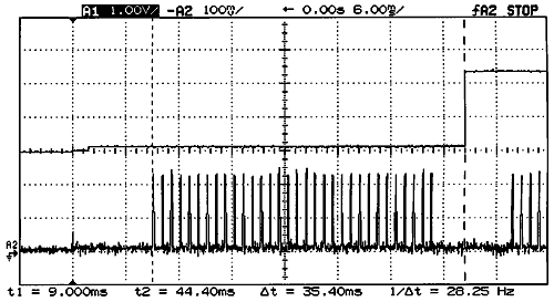
Top trace: Output of
GP2D12
Bottom trace: Current
absorbed (100 mA per graduation)
A 5V power supply is connected to GP2D12
through 1 ohm resistance to measure current.
Power is applied to sensor at t=0. At t1=9ms,
it begins to emit 32 pulses of light, each
requiring about 220 mA. Output is valid
at t2=44.4ms. |
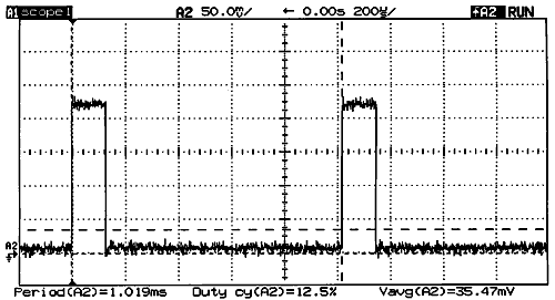
Zoom on GP2D12 current
pulses.
These pulses have a 1/8 duty cycle, interval
between them is 1ms.
Average current is 35.5 mA = 220mA/8
(current pulses) + 7/8*9mA (constant current).
Actually average current is lower since
pulses don't occur during the first 9 ms |
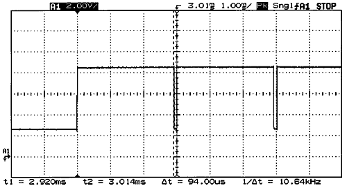
RCX sensor input, connected
to a 10K resistor
At t<0, sensor is programmed as a
passive sensor. Tension is constant and
equal to 2.5V (5V RCX output divided by
2 because of 10K internal output.
At t>0, sensor is an active sensor,
providing 8.5V on its output. Every 3ms,
RCX polls the output of the sensor, switching
it to passive mode for 94µs. Note
that during that time GP2D12 will be powered
(see below). |
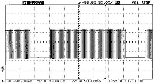
RCX sensor input, connected
to a 10K resistor (zoomed out)
Sensor mode is programmed (theoretically)
50 ms in passive mode, 250 ms in active
mode (See main page program). As you can
see, result is not very precise, since passive
phase last 63 ms and active one 260 ms... |
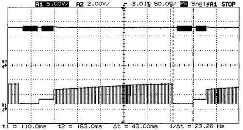
GP2D12 module connected to RCX sensor
input
Top trace: Output of TC55
regulator
Bottom trace: Voltage
across sensor terminals
You can see "grass" on regulator
output while GP2D12 pulses its IR led (C2
doesn't filter enough). Apart from that,
regulation is good. Bottom trace shows voltage
rising slowly as C1 charges in active mode,
then, in passive mode, output of sensor
that becomes valid after 43ms. |
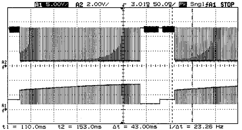
GP2D12 module connected to RCX sensor
input
Top trace: GP2D12 power
supply
Bottom trace: Voltage
across sensor terminals
The interesting point here is the comb
observed across GP2D12 supply while charging
C1. In fact, (see above) RCX switches its
output to passive mode 94µs each 3ms.
During this time, Q1 conducts and GP2D12
is powered. However average current is quite
low, since GP2D12 has not enough time to
begin emitting pulses: I = 9mA * 94/3000
= 0.28mA. |
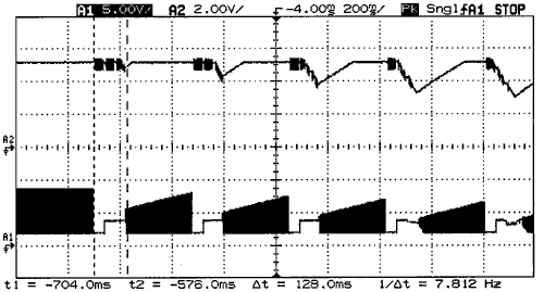
GP2D12 module connected to RCX sensor
input
Top trace: Output of TC55
regulator
Bottom trace: Voltage
across sensor terminals
Here I increased passive time to a too
long time (128ms), C1 discharges too
much so charge time is too short to restore
full voltage. As we start with full charge,
we can see progressive degradation. Some
interesting informations can be derived:
- Passive time must be as short as
possible (but not shorter than GP2D12
conversion time !)
- Output of regulator follows nicely
its input when this one is insufficient.
- Output of GP2D12 is valid even with
power supply as low as 4V (datasheet
specifies it down to 4.5V)
|
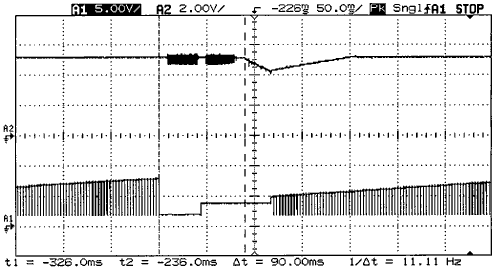
GP2D12 module connected to RCX sensor
input
Top trace: Output of TC55
regulator
Bottom trace: Voltage
across sensor terminals
Zoom on previous trace: regulator output
drops below 5V only after 90ms |
![]()
![]()
![]()
![]()

![]()

![]()
![]()
![]()