![]()
![]()
![]()
![]()

![]()
![]()
![]()
![]()
![]()
![]()
![]()
![]()
![]()
![]()
![]()
- Communication occurs on pin 5 and 6 of Powered Up connector (ID1/ID2 lines). ID1 (pin 5) transmits data from hub to device, ID2 (pin 6) transmits data from device to hub.
- Communication uses asynchronous serial protocol (UART).
- When the devices are powered on, there is an initialization sequence that occurs at 2400 bits/s.
- After the initialization, serial link switches to 115200 bits/s for "data mode", during which the device sends data and receives polling and commands to the hub.
The Powered
Up serial link protocol
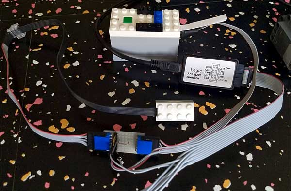
Curious to see how the dialog between Powered Up elements and hubs were communicating, I hooked a logical analyzer to the cable between them. Here is what I found...
![]() Next to this icon you'll be able
to find analyzer capture files for a few devices/situations.
With them, you'll be able to perform your own protocol reverse
engineering! To explore these captures, you'll need Sigrok/Pulseview
open source signal analysis software.
Next to this icon you'll be able
to find analyzer capture files for a few devices/situations.
With them, you'll be able to perform your own protocol reverse
engineering! To explore these captures, you'll need Sigrok/Pulseview
open source signal analysis software.
Initialisation phase
I haven't spent too much time trying to understand what happens during this phase that occurs after power on of the system. During this phase, communication occurs at 2400 bits per second. Strangely enough, I get framing errors in hub to device direction. It could be using a 9 bits format... Anyway, data is mostly sent in device to hub direction.
Here is a screenshot of the overall initialization
exchange, between Powered Up hub and Control+ XL motor.
About 500 bytes are returned by the motor.
|
|
|
|
|
|
...and a close up of the start of dialog:
Looking at device data in ASCII mode reveals some text strings that seems to indicate that the device sends a description of data that will be available during data phase.
Device |
Strings |
|
|
|
|
||||||
Control+ XL motor |
STATS |
CALIB |
APOS |
POS |
SPEED |
POWER |
G836660 |
|
|
|
|
Control+ L motor |
STATS |
CALIB |
APOS |
POS |
SPEED |
POWER |
G834061 |
|
|
|
|
Boost motor |
TEST |
POS |
SPEED |
POWER |
|
|
|
|
|
|
|
WeDo 2 distance sensor |
LPF2-CAL |
LPF2-COUNT |
LPF2-DETECT |
|
|
|
|
|
|
|
|
WeDo 2 tilt sensor |
LPF2-CAL |
LPF2-CRASH |
LPF2-TILT |
LPF2-ANGLE |
|
|
|
|
|
|
|
Boost color sensor |
CALIB |
DEBUG |
SPEC |
IR |
RGB |
COL |
AMBI |
REFLT |
COUNT |
PROX |
COLOR |
Data phase
After the initialization phase, the serial link switches to a much higher speed, 115200 bits/s. The host polls the device every 100 ms (sending a single 0x02 byte), the device answers with data frame. If device value(s) change between polls, the device sends a data frame without solicitation from the hub. Data frame contains a start of frame byte (depending on device), then data byte(s) and a checksum byte (Checksum8, NOT(XOR of previously transmitted bytes)). Multi-byte values are sent low byte first (in the example below, accumulated angle is 0x1091 = 4241).
As an example, here is an exchange between hub and Boost motor.
WeDo distance sensor
|
Example frame |
Data type |
Contents |
Range |
C0 |
Byte |
Start of frame |
|
|
01 |
Unsigned byte |
Distance |
0..9 |
|
3E |
Byte |
Checksum |
|
"Distance" is actually an indication of reflected light. 0 is no reflected light, 9 can be reached with the sensor placed 5mm above a white paper.
WeDo tilt sensor
|
Example frame |
Data type |
Contents |
Range |
C8 |
Byte |
Start of frame |
|
|
02 |
Signed byte |
X tilt angle (degrees) |
-45..+45 |
|
2D |
Signed byte |
Y tilt angle (degrees) |
-45..+45 |
|
18 |
Byte |
Checksum |
|
X direction is the rotation around long side of the brick. Value is clipped at +/-45°.
![]() WeDo
2 tilt sensor data phase.
WeDo
2 tilt sensor data phase.
Boost color and distance sensor
This has a more complex behavior: not only it accepts commands from the hub to control LED color, but after poll it answers with a 3 bytes frame (0x46, 0x08, 0xB1), immediately followed by the true data frame returning data. This data frame is also sent (alone) when sensor values change.
Command |
Example frame |
Data type |
Contents |
Range |
|
46 |
Byte |
Start of frame |
|
08 B1 D0 00 00 |
Bytes |
??? Unknown meaning |
|
|
03 |
Byte |
LED color |
0, 3, 5, 9, 0x0A |
|
00 |
Byte |
??? Unknown meaning |
|
|
2F |
Byte |
Checksum |
|
![]() Boost
color sensor data
phase during LED color change.
Boost
color sensor data
phase during LED color change.
Data |
Example frame |
Data type |
Contents |
Range |
|
D0 |
Byte |
Start of frame |
|
0A |
Byte |
Detected color |
0, 3, 5, 9, 0x0A, 0xFF |
|
01 |
Byte |
Distance |
0..10 |
|
03 |
Byte |
LED current color |
0, 3, 5, 9, 0x0A |
|
59 |
Byte |
Reflected light |
0..5F |
|
2F |
Byte |
Checksum |
|
Color codes:
00 |
Black / LED off |
03 |
Blue |
05 |
Green |
09 |
Red |
0A |
White |
FF |
No object |
Note that reflected light value is scaled to a 0..10 range in Powered Up app by dividing by about 9 the value returned by sensor.
![]() Boost
color sensor data
phase during color detection.
Boost
color sensor data
phase during color detection.
Boost motor
|
Example frame |
Data type |
Contents |
Range |
D8 |
Byte |
Start of frame |
|
|
1E |
Signed byte |
Rotation speed (%) |
-125..125 |
|
00001091 |
Signed Dword |
Accumulated angle (degrees) |
+/- 2.109 |
|
0000 |
Word |
0 |
|
|
00 |
Byte |
0 |
|
|
B8 |
Byte |
Checksum |
|
Rotation speed is calibrated to 100% when the motor is powered at full speed with nominal voltage (9V). You can reach higher values (up to 125%) by manually turning the motor shaft. According to the strings in initialization phase, last data byte might be power in %, but this byte is always 0, and anyway the motor has no way to know the power applied to it. Reserved for future use?
![]() Boost
motor data phase
during manual rotation of hub.
Boost
motor data phase
during manual rotation of hub.
Control+ motors (L and XL)
|
Example frame |
Data type |
Contents |
Range |
D8 |
Byte |
Start of frame |
|
|
D7 |
Signed byte |
Rotation speed (%) |
-125..125 |
|
FFFFFDBA |
Signed Dword |
Accumulated angle (degrees) |
+/- 2.109 |
|
FFCF |
Signed Word |
Absolute angle position (degrees) |
-180..179 |
|
00 |
Byte |
0 |
|
|
B8 |
Byte |
Checksum |
|
The data frame is the same as the Boost motor, with added absolute angle position derived from a magnetic angle sensor placed on the output shaft.
![]() Control+
XL motor data phase
during speed ramp-up
Control+
XL motor data phase
during speed ramp-up
![]()
![]()
![]()
![]()
![]()
![]()
![]()
![]()
![]()
![]()
![]()
![]()
![]()
![]()
![]()