![]()
![]()
![]()
![]()

![]()
![]()
![]()
![]()
![]()
![]()
![]()
![]()
![]()
![]()
![]()
Lego® Rotation Sensor Internals
Important note: Take care of your fingers too... Do it at your own risk and only if you know what you are doing!!! |
Lego rotation sensor is a nice little device that enables RCX to measure rotation of an axle with good resolution: 16 steps per turn. Unfortunately it is plagued with a problem: at low rotation speed value read seems to jump randomly from 1 or two units. So I decided to have a fairly indiscrete look at it... here is what I discovered.
Active sensor working
 Active sensors (rotation
sensor, light sensor) communicate with RCX through a two phases
scheme: during 2.9ms, RCX powers sensor (+8V), then during about
100µs RCX reads analog value returned by sensor. During
read phase, no power is provided to sensor, and this one has
to live on its own reserve. This is done by storing energy in
a capacitor during power phase.
Active sensors (rotation
sensor, light sensor) communicate with RCX through a two phases
scheme: during 2.9ms, RCX powers sensor (+8V), then during about
100µs RCX reads analog value returned by sensor. During
read phase, no power is provided to sensor, and this one has
to live on its own reserve. This is done by storing energy in
a capacitor during power phase.
A 10K ohm resistor inside RCX pulls up sensor output to +5V, sensor has to absorb current to drop voltage to desired value.
Rotation
Sensor
 Here
is a zoom on read phas of a rotation sensor. Numerous traces
are accumulated over some time while rotating axle of sensor.
You can see that sensor communicates with RCX through a 4 levels
code. The voltages I measured for this levels are:
Here
is a zoom on read phas of a rotation sensor. Numerous traces
are accumulated over some time while rotating axle of sensor.
You can see that sensor communicates with RCX through a 4 levels
code. The voltages I measured for this levels are:
Step 1 |
1.3 V |
Step 2 |
3.3 V |
Step 3 |
2.0 V |
Step 4 |
4.5 V |
These values seem a bit low when compared to Michael Gasperi's (see his rotation sensor page), perhaps my batteries were exhausted. You can also see that there is some jitter in read phase duration (between 90µs and 125µs)
Dick Swan offered me more precisions on this jitter, see here.
 As
the axle is rotated clockwise, output cycles througs steps 1
> 2 > 3 > 4 > 1, and through steps 1 > 4 >
3 > 2 > 1 when rotated ccw. This enables RCX to determinate
rotation direction.
As
the axle is rotated clockwise, output cycles througs steps 1
> 2 > 3 > 4 > 1, and through steps 1 > 4 >
3 > 2 > 1 when rotated ccw. This enables RCX to determinate
rotation direction.
As pointed out by here by Jürgen Stuber, we have here the first problem of rotation sensor: during transition between step 3 and 4, output crosses voltage of level 2, and between step 1 and 2, output crosses voltage of level 4. Since this transition takes some time, there is a probability that it happens just when RCX samples value. I tried to determine sampling time, it seems to take place about 60µs after beginning of read phase.
Dick Swan made an experiment showing that step
1 is longer than the three others. See here
his measurements and an explanation.
 Here is such a transition between
step 3 and step 4. We can see that transition time across 3.3V
(step 2) can be evaluated to 1µs. Sampling is done every
3 ms, probability of misread can be evaluated to about 1/3000
at most.
Here is such a transition between
step 3 and step 4. We can see that transition time across 3.3V
(step 2) can be evaluated to 1µs. Sampling is done every
3 ms, probability of misread can be evaluated to about 1/3000
at most.
Some alternative RCX programming languages (legOS and leJOS) perform two consecutive readings and almost eliminate this problem at the cost of halving maximum rotation speed.
But the mechanism of this problem is independent
of rotation speed. So why are worse at very low rotation speed
? Read on...
Problems at low speed
 To obtain this trace, I simply rotated
sensor by hand very slowly till I reached transition between
steps. And instead of having a sudden jump between two values,
I got a stable oscilloscope trace (hand shaking apart) showing
a transition each 3ms! And moving VERY little my hand I could
modify the position of this transition, and especially place
it just at sampling point - and counter began to jump between
values.
To obtain this trace, I simply rotated
sensor by hand very slowly till I reached transition between
steps. And instead of having a sudden jump between two values,
I got a stable oscilloscope trace (hand shaking apart) showing
a transition each 3ms! And moving VERY little my hand I could
modify the position of this transition, and especially place
it just at sampling point - and counter began to jump between
values.
It seems that very close to transition position, there is synchronisation with power/read cycle, and this increases the previous problem: there is a lot of transitions instead of only one - and when rotating very slowly this transition is doomed to occur at sampling point and cause misread. Note that even double sampling as performed by legOS and leJOS has no guarantee to give correct answer: if rotation is very slow two successive reads will happen during transition...
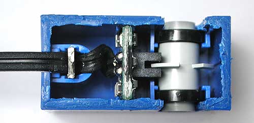
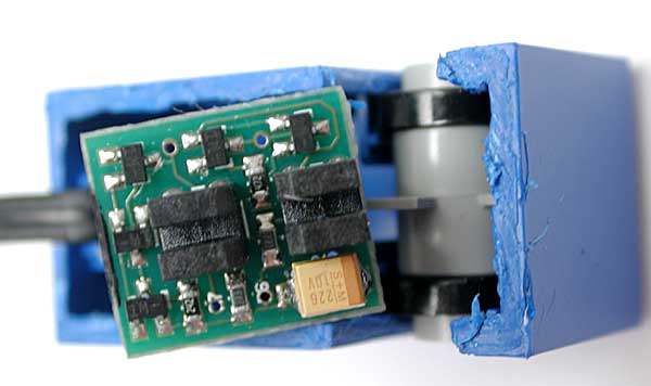
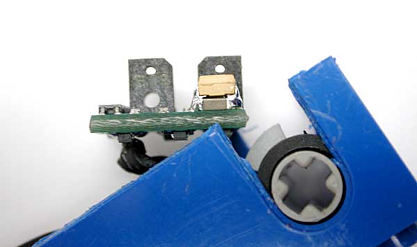
Opening the sensor
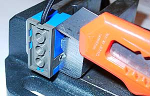 To go further, I needed
to look inside the sensor. Prying it open proved painful. I
first cut the blue tabs below the baseplate, but sensor didn't
open. It seems that some tabs are glued or heat soldered, so
I had to resort to brute force methods and cut everywhere between
dark grey and blue parts. Moreover the wire is locked tight
in upper part by a peg belonging to grey plate, and I had to
cut that peg too.
To go further, I needed
to look inside the sensor. Prying it open proved painful. I
first cut the blue tabs below the baseplate, but sensor didn't
open. It seems that some tabs are glued or heat soldered, so
I had to resort to brute force methods and cut everywhere between
dark grey and blue parts. Moreover the wire is locked tight
in upper part by a peg belonging to grey plate, and I had to
cut that peg too.
If someone finds a more elegant method to open this shell please let me know!
(Photo courtesy of Andreas Peter)
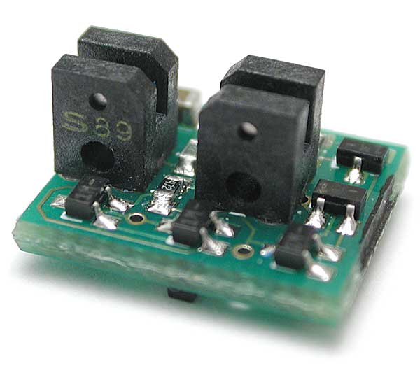
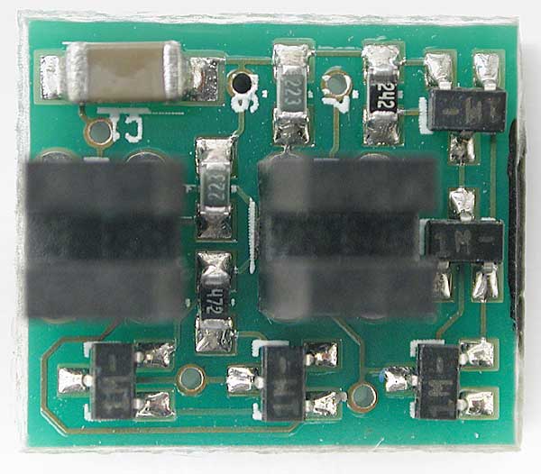
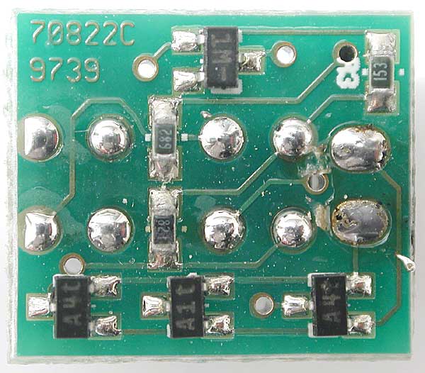
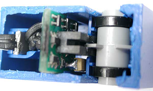
Inside
sensor
A few pictures are worth a
thousand words...
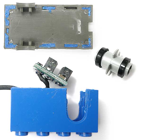
Circuit board schematics and analysis
D1, D2 rectify power supply, C1 filters it. K1 and K2 are two opto-forks (marked S89, I didn't found exact part type), one side contains an infra-red led, the other side a phototransistor. Blade of propellar shape part can interrupt infrared beam of K1, K2, both or none, providing the four phases of the returned value. Since there are 4 blades, we obtain 16 steps per turn. IR leds receive power through R1 (about 5mA). The node between R1 and K1 led is maintained at a 2.2V constant voltage (drop across 2 IR leds. Output of phototransistors are amplified by high gain Darlingtons (Q1, Q2) and (Q3, Q4). Their output drives the base of Q5/Q6, whose base is polarized to the previous 2.2V reference through R4 and R5. Through D3, Q5 and Q6 absorb current provided by 10K ohm resistor inside RCX, and generate the 4 levels:
|
Vout |
Q5 |
Q6 |
Step 1 |
1.3V |
ON |
ON |
Step 2 |
3.3V |
OFF |
ON |
Step 3 |
2V |
ON |
OFF |
Step 4 |
4.5V |
OFF |
OFF |
May 2006 update: Ian Davis spotted a mistake on my schematics, a missing link between emitter of Q5/Q6 and base of Q1/Q4. This link seems to provide some feedback and helps getting the correct output voltages.
Solving
the problems
A radical method would
be to prevent output transition while RCX is sampling data.
If space was not at a premium inside rotation sensor, this could
easily be done by insertind D-type flip-flops (CD4013) between
Darlington outputs and Q5/Q6 bases, clocked at the end of data
read phase. But here it is almost impossible, and anyway at
reasonable speed lost count seems very rare. So I only tried
to improve only low speed behaviour.
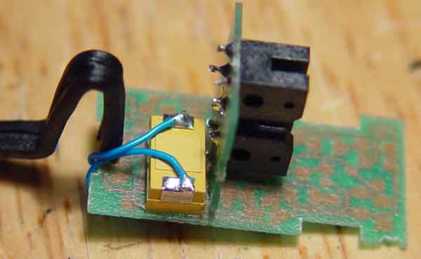
Since problem is caused by synchronisation between supply and amplifier threshold, I tried to increase power supply filtering. I added a tantalum 22µF 10V capacitor in parallel with C1 and tried my modified sensor... Yippee! it now works perfectly even with looooow speed rotation, no more erratics counts, no more signal synchronisation seen on my oscilloscope.
Modified sensor photos
Dan Walkowski sent me photos of a rotation sensor with different construction (older model ?). These images show how he applied the fix.

... and I repeat the disclaimer:
Important note: Take care of your fingers too... Do it at your own risk and only if you know what you are doing!!! |
![]()
![]()
![]()
![]()
![]()
![]()
![]()
![]()
![]()
![]()
![]()
![]()
![]()
![]()
![]()