![]()
![]()
![]()
![]()

- Copy or mirror repetitive stuff using MLCad or another program.
- Use Txt2Dat to create the text section of a sticker.
- Retrieve special templates (not included in Quad2Dat) from a LDraw file.
- Etc ...
- Dat2QP checks that projected polygons are valid, and removes degenerated forms (common vertices), but does not check for 3 aligned vertices.
- To keep things simple, lines in the generated file are not ordered, and vertices with identical coordinates are kept separated.
- If you want to get a sorted .qp file with identical vertices suppression, just load and save the file with Quad2Dat.
- Dat2QP does not convert primitives (disc, ndis, ring, ...) since because of value rounding in Quad2Dat adjacent polygons might not have exactly the same coordinates.
- Version 1.1 : Projection direction added, checks added, suppression of degenerated polygons.
- Version 1.0 : Initial Version.
|
Dat2QP: LDraw to Quad2Dat converter
Dat2QP is a tool written in C++ by J.C. Tchang. It allows to convert a LDraw file into a Quad2Dat one.

Dat2QP sample run, showing usage.
Purpose of the program
Quad2Dat is a program written by Chris Alano, allowing creation of patterns for LDraw parts. Despite many imperfections and crashes, this tool remains the best in its category. Thanks, Chris. You may download it here.
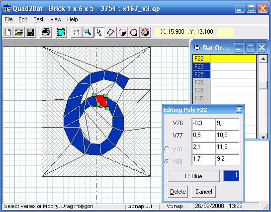
Quad2Dat sample
run.
The purpose of Dat2QP tool is to allow recovering existing LDraw patterns to easily modify or complete them using Quad2Dat.
Dat2QP converts 3D quads or triangles to 2D (projection on a plane) and writes the result using Quad2Dat file format (.qp). You may choose projection direction along X, Y (default) or Z axis.
Another use of Dat2QP is to allow use of tools outside Quad2Dat, such as :
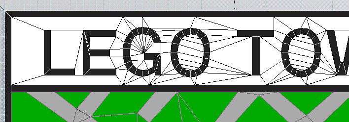
Duplication example: the first "O"
letter was created with Quad2Dat, then duplicated with
MLcad before creating the white background.
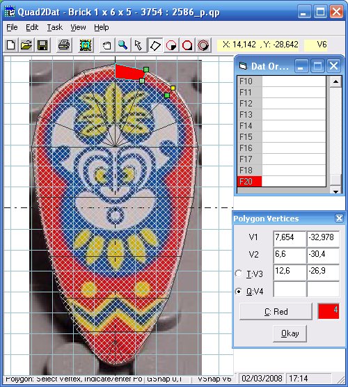
Example of special template: the shape is retrieved
from 2586.DAT, after inlining disc primitives using LDDP, and
converting the result with Dat2QP. Here we can see the
selection of a vertex on the edge of the shape (V6).
Download
Dat2QP package, including Windows program, source file and this documentation.
No installation is required, just unzip the archive and copy the executable file (dat2qp.exe) in a directory. For example, I use folder c:\lego\dat2qp.
Note: Macintosh version (universal binary) courtesy of Jim DeVona.
Usage
Creation of input file
Your input file should contain the facets to be processed, that is to say triangles (type 3) and/or quads (type 4). Dat2QP doesn't manage primitives (type 1) that must be inlined by a tool such as LDraw Design Pad (LDDP).
Place this file in the install folder of Dat2QP, e.g. in c:\lego\dat2qp.
Converting with Dat2QP
Open a "Command prompt" window (DOS box on older
systems), then go to Dat2QP install folder: type the
command cd c:\lego\dat2qp, or if you
are not a command prompt wizard, just type cd
followed by a space character, then from a Windows explorer
opened on Dat2QP install folder, drag and drop the folder
icon from the address bar onto the command prompt window, select
this window and hit
Type in the command:
dat2qp [-x |
-y | -z ] input_file.dat output_file.qp
for example
:
dat2qp -y test1.dat test1.qp
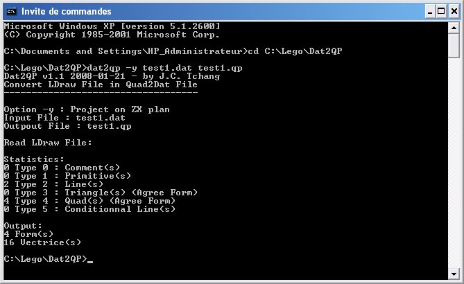
Sample use.
Using the output file with Quad2Dat
You may then use the output file, test1.qp for example, with Quad2Dat.
Note : if you get this error message when opening the file in Quad2Dat: "Run-time error '13': Type mismatch", your system is setup with a comma "," instead of dot "." as fractional part separator. Use your favorite text editor to replace all commas "," with dots ".".
The default template used by the conversion is the 1x6x5 brick. If the facets converted with Dat2QP do not fit the template, just hide it in Quad2Dat options: View / Options..., than in "Display" tab, uncheck "Template".
See Quad2Dat manual for more information.
Warning: SAVE OFTEN under different names when using Quad2Dat, because it crashes in many case with lost of the data previously recorded.
Dat2QP characteristics
Integration of Dat2QP into LDraw Design Pad
You may launch Dat2QP from LDraw
Design Pad after creating the 3 .bat files below:
In
dat2qp-x.bat :
cd c:\lego\dat2qp
dat2qp -x %1 %2\dat2qp-x_result.qp
In dat2qp-y.bat :
cd c:\lego\dat2qp
dat2qp -y %1 %2\dat2qp-y_result.qp
In dat2qp-z.bat :
cd c:\lego\dat2qp
dat2qp -z %1 %2\dat2qp-z_result.qp
Note: The files must be placed in the folder indicated in "Path & Filename:" field of the dialog boxes below. In these example it is the LDDP Plugins folder
Then setup LDDP as follows:
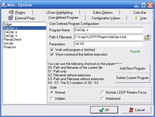
To convert LDDP active
file along X direction
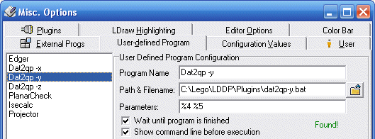
To convert LDDP active
file along Y direction
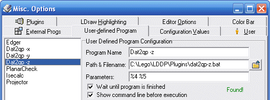
To convert LDDP active
file along Z direction
Once properly configured, you may launch Dat2QP within LDDP
from the menu Process/External Programs/User Defined Program,
or using "User Defined Program" icon in the "External
Programs" toolbar:
![]()
Conversion result is in file dat2qp-x_result.qp, or dat2qp-y_result.qp, or dat2qp-z_result.qp, placed in the same directory as the original file.
Intégration de Dat2QP dans LETGUI
You may launch Dat2QP in a way more user-friendly than command line. That's the purpose of LETGUI, created by Michael Heidemann.
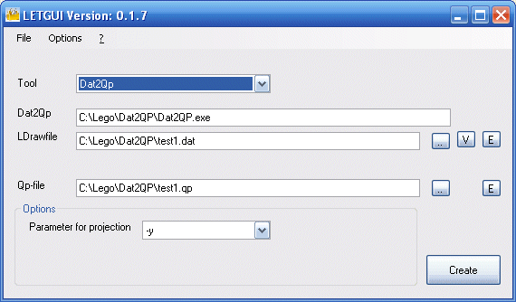
Tutorial: a concrete example
Browsing through LDraw parts library for the 1x1 brick with "6" I realize that this brick exists in two versions, one of them (3005-6.DAT) fits my needs.
Looking at this part with LDView, I see that this part is not perfect. Facets overlap, and there is a gap. I decide to improve it.
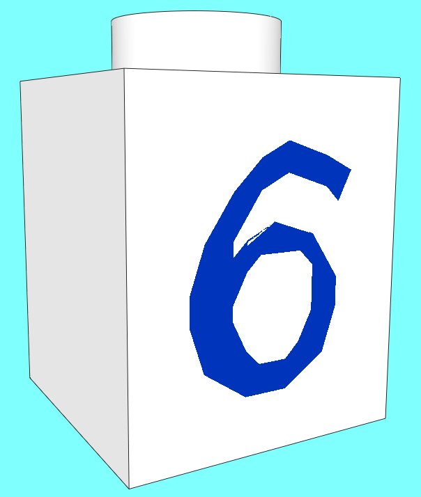

(Click on left
side image to enlarge).
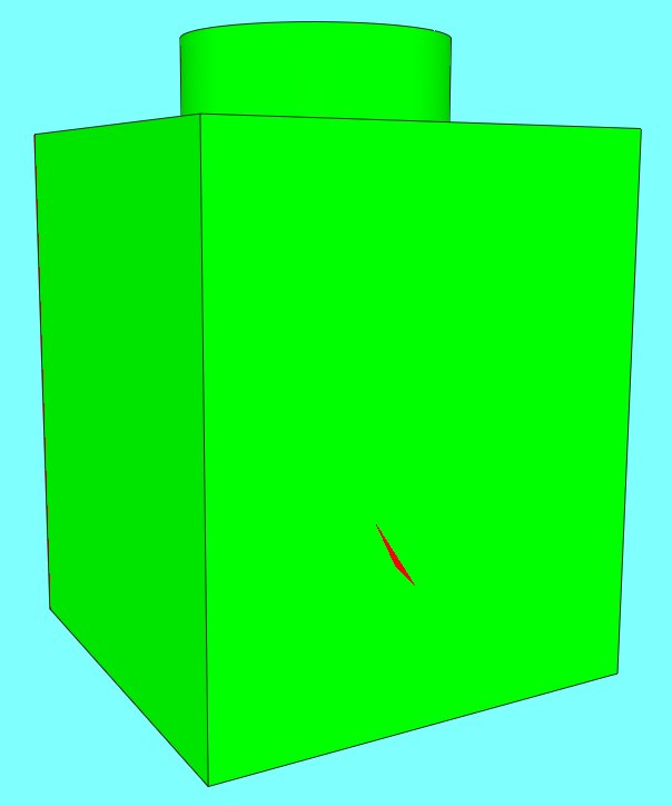
LDView BFC compliance
test shows missing facet.
(Click on image to enlarge).
First I replace all faces and stud with subpart s\3005s01.dat
without front.
Doing so I noticed that the bottom of the
part was wrong. Using standard subparts avoid this kind of issues.
Then I convert the Ldraw file to Quad2dat using -z projection direction
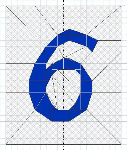
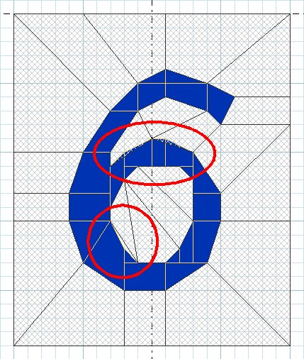
A first glance with Quad2dat show two overlapping areas, and a missing triangle.
I suppress wrong facets and rebuild missing parts with quads and triangles of the right color.
Now we can go further and suppress T junctions, always with
the same method: delete facets and recreate them right.
Saving and reloading the file maybe helpful to suppress duplicated
vertices.
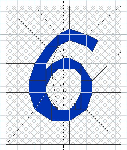
We can then move some vertices to smooth letter
curves, without adding new facets
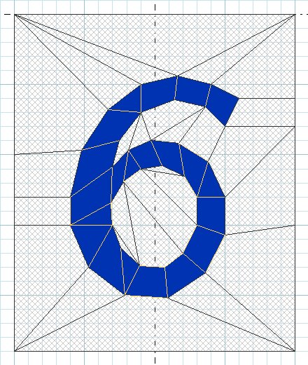
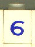
(Click on left
side image to enlarge).
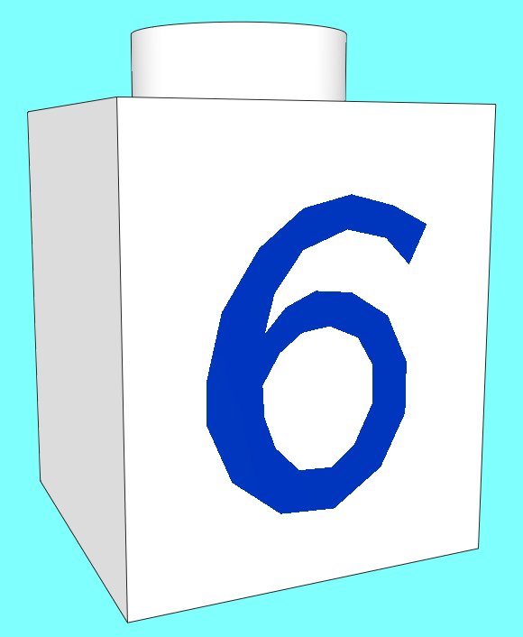
This is not perfect, but looks like a bit more to right side photo. I didn't try to get exactly the same character height as there was many font variants used on this part year after year.
After a LDraw export and replacing the result in complete part file, we get our updated part.
Copyright
(c) J.C. Tchang - 2008
French Manual: J.C. Tchang. English translation: Philo
Free for any non-commercial use. :-)
|
![]()

![]()
![]()
![]()
