![]()
![]()
![]()
![]()

- V1.0: Initial release
- V1.1: Improved file output format (July 2008)
- V1.2: Added command line switches allowing to work in any Y, Y or Z direction.
- V1.3: Added radial distance mode (April 2009)
- V1.4: Corrected a command line parsing bug. (Oct. 2009)
- Prepare the input LDraw files. Ytruder uses only lines of input files (line type 2). Other LDraw line types are ignored. If you want to compute surface between edge primitives, they must be inlined down to lines. LDDesignPad does this very conveniently.
- Launch a command prompt
- Type the command line: ytruder [-d or -s or -p or -r <val>] [-x, -y or -z] [-a <angle>] LdrawLineFile LdrawSurfaceFileOut. Ytruder will create LdrawSurfaceFileOut, containing the surface. Note that if file LdrawSurfaceFileOut exists it will be overwritten without warning. -x, y and -z control the direction of operation. -d, -s, -p, -r and -a are optional parameters controlling the behavior of Ytruder These options will be detailed below.
- Ytruder outputs file with 6 digits after decimal point, this precision is excessive for most usages and values should be rounded. Here again, LDDesignPad does that very well.
- Input file is read and parsed. All line apexes are stored in an array (limited to 1000 lines, should be more than enough!).
- Lines are scanned to find the start of a path (a path is defined as consecutive lines whose ends are "close enough").
- Path is explored from start to end, creating surfaces and conditional lines in the process, they are stored in arrays. The orientation of surfaces is maintained along a path, easing building of BFC conformant parts.
- Each surface is built over a line in the path and on
a second one, obtained from the first depending on parameter:
- -d <val>: Line is translated by distance <val> in direction X, Y or Z depending on the specified -x, -y or -z parameter (-y is the default)
- -s <val>: Second line is obtained by symmetry across plane X, Y or Z=<val>. Ytruder default is symmetry across plane Y=0.
- -p <val>: Second line is obtained by projection on plane X, Y or Z=<Yval>
- -p <val>: Second line is obtained by radial extrusion by distance=<Yval> from direction axis
- Lines are added at the start and end of each path. Line array is scanned for yet unused line paths.
- Output file is written. During this process
- Quads that have 2 identical apexes are transformed into triangles, degenerated quads and conditional lines are suppressed.
- Conditional lines that are between two surfaces with an angle above -a <angle> threshold are converted to simple lines. Ytruder default is a 30° threshold.
Examples
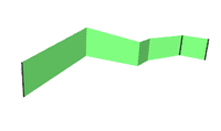
Parallel extrusion.
Files: ytline.dat --> ytsurf-d6.datCommand line: Ytruder -d 6 ytline.dat ytsurf-d6.dat
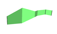
Symmetrical extrusion.
Files: ytline.dat --> ytsurf-s0.dat
Command line: Ytruder -s 0 ytline.dat ytsurf-s0.dat
or Ytruder.exe ytline.dat ytsurf-s0.dat (-s 0 is the default)
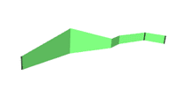
Projection extrusion.
Files: ytline.dat --> ytsurf-p0.dat
Command line: Ytruder -p 0 ytline.dat ytsurf-p0.dat
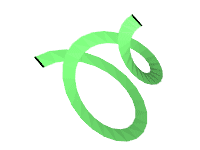
Radial extrusion.
Files: spiral.dat --> screw.dat
Command line: Ytruder -r 5 spiral.dat screw.dat

With angle threshold set to 0°, a fixed line is created at each surface junction.
Files: ytline.dat --> ytsurf-s0a0.datCommand line: Ytruder -s 0 -a 0 ytline.dat ytsurf-s0a0.dat

With angle threshold set to 180°, only conditional lines are created at each surface junction.
Files: ytline.dat --> ytsurf-s0a180.datCommand line: Ytruder -s 0 -a 180 ytline.dat ytsurf-s0a180.dat

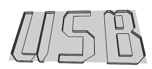
A real life example, from the NXT engraved lettering I created recently using Ytruder.
Files: usbline.dat --> usbside.dat
Command line: Ytruder -d 0.5 usbline.dat usbside.dat
The result, after addition of top and bottom surfaces. The method used is detailed in this tutorial (file usb-final.dat)
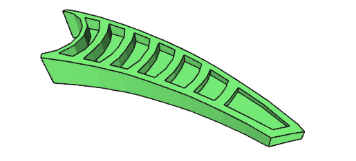
Another part section, tip of 50914. Building this part is detailed in this tutorial: Building shapes with Quad2Dat, Edger and Ytruder
|
Ytruder, LDraw extruder
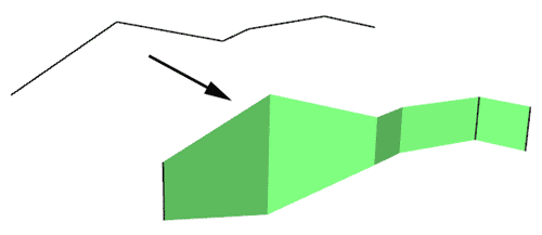
Ytruder utility creates a sheet of triangle and quads from a set of lines. This is done by extrusion in the specified LDraw direction. Though somewhat similar to Coverer it has a few other possibilities, such as the capability to handle several distinct paths of lines at the same time. The set of lines is provided to the utility as a LDraw file. A second file containing the surface (and its fixed and conditional lines) is created.
Name comes from initial version that worked only in Y direction...
It is a simple console application, source code is provided below to anyone willing to integrate it in a more palatable interface. You may also use Michael Heidemann LETGUI front-end (highly recommended!).
Download
Ytruder package, including program for Windows, documentation, source files (Visual C++ 6.0), sample files.
Note: Macintosh version (universal binary) courtesy of Jim DeVona.
History
Usage
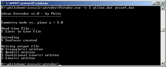
Here is a screen shot of a sample run:
How Ytruder works
|
![]()

![]()
![]()
![]()
