![]()
![]()
![]()
![]()

![]()
![]()
![]()
![]()
![]()
![]()
![]()
![]()
![]()
![]()
![]()
- when the needle makes an angle too low with the object surface, the needle slips. The acquired points in these area have low precision and must be deleted before assembly. I used two techniques to minimize this problem: sharpen the needle as much as possible, and spray repositionable glue ("Post-it®") on the part. No damage on the part: pressure is so low that there is no needle marks, and rubbing with alcohol after scan easily removes glue.
- On some scan I have seen a slow drift of the probe zero. This results in slanted scans and scaling issues between scan in different directions. This makes reconstruction of the object much more difficult. I tracked down this issue to a drift in NXT motor encoder itself. After doing a lot of back and forth moves (during a scan the probe shuttles several thousands times!) the zero of the encoder does not correspond to the same mechanical position of the shaft. Depending on the scan parameters, this issue is barely noticeable or make the scan useless. I have not yet tried to add a periodic recalibration of zero position.
- The scanning process is very slow, several hours for a small part! Since NXT motors are rather noisy (and the very repetitive noise is especially nerve-racking), I placed the scanner in my garage and do the scans by night or while being at work...
- Split in half to reduce size
- slice bottom to get a flat base
- insert a stud hole in the base
- replace the too smooth eyes bump with a cone and sphere to restore frog character - the scan was not fine enough to keep these minute details.
|
NXT
3D scanner
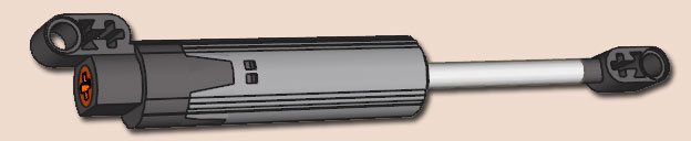
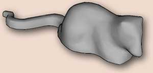
I am a LDraw parts author, and as such I am always interested to find new ways to model LEGO parts. Many parts have a clear geometric structure and are relatively easy to create, but parts like the frog pictured above have no defined geometric shape and are very difficult to model. I toyed for a while with the idea of a 3D scanner... The solution came with 2008 LEGO Technic sets that include a new part, the linear actuator. These nifty device convert the rotation movement of a motor into a linear movement. Coupled with the high resolution of NXT encoder, I had all the elements to build a 3D scanner, precise enough for my purpose.
|
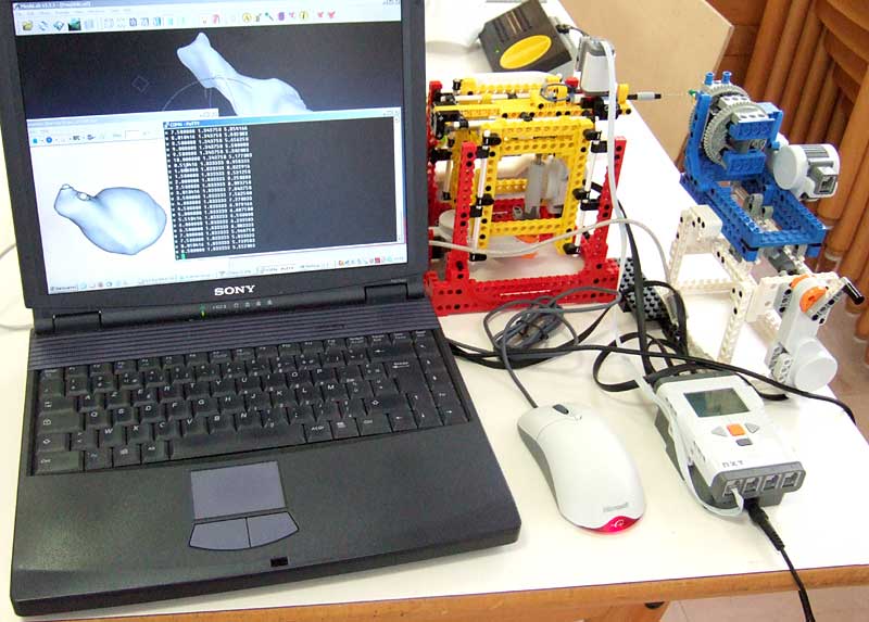
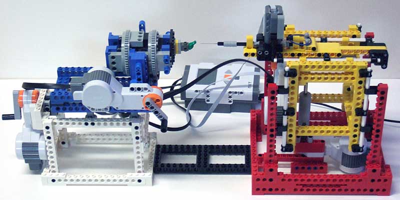
Full setup with the laptop gathering data. |
|
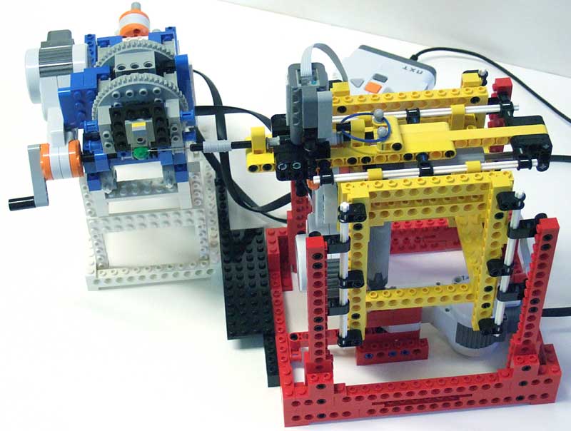
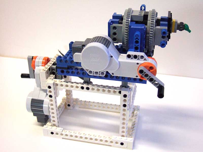
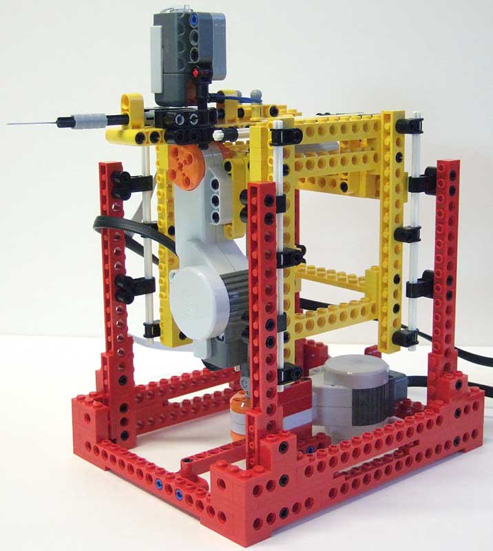
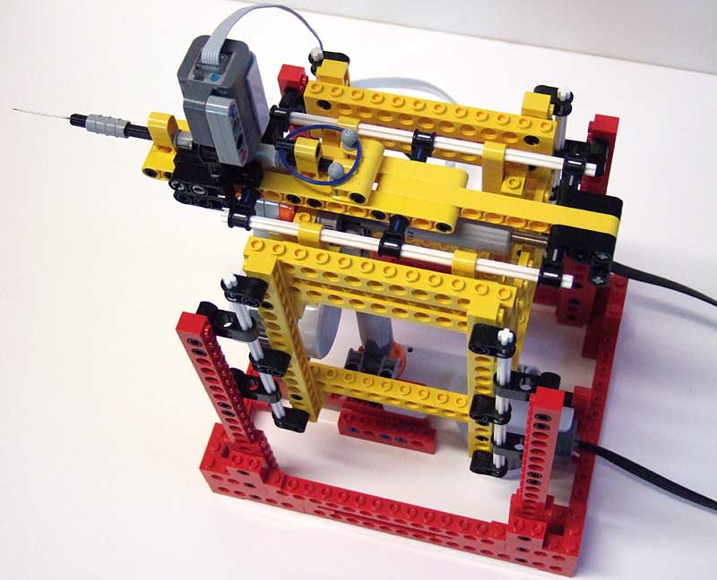
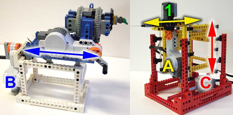
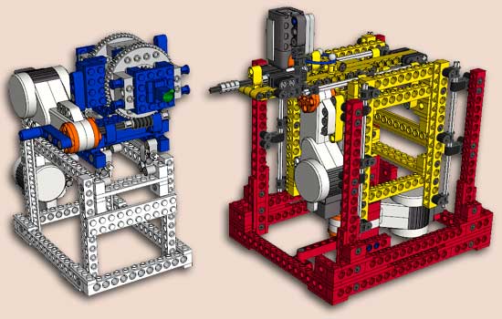
The complete scanner, showing all modules. The probe module (red/yellow) moves the probing needle back and forth as well as up and down. When the probe needle touches the object, the location of the contact point is recorded. The object module (white/blue) is able to move back and forth the object and rotate it. All the movements combined provide either a cartesian or a cylindrical scan. |
|
Side view of the object module. The rear motor drives a linear actuator (LA) which moves the object carrier. Motor is directly coupled to LA to minimize gear backlash. The carrier bears a turntable, driven by a second motor through a worm gear. Note the use of two stacked turntables to avoid wobble caused by mechanical play. |
|
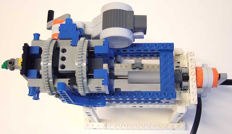
Top view of object module. Though the scanner as shown uses 4 motors, only 3 are needed at the same time for a given style of scan. So only one NXT is needed to drive the scanner. If you decide to use only X-Y-Z scans, turntable assembly and 4th motor can be removed and replaced by a simpler chassis. Anyway I have not yet written the cylindrical scan software! |
|
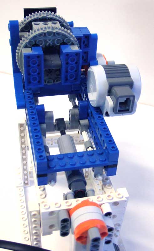
Back of the turntable assembly. |
|
The object is fixed to the turntable by any suitable mean of plates, jumpers, bricks... |
|
The probe module. Two linear actuators are used here, again directly driven by NXT motors. Axles sliding in Technic holes are used to guide precisely the movements. |
|
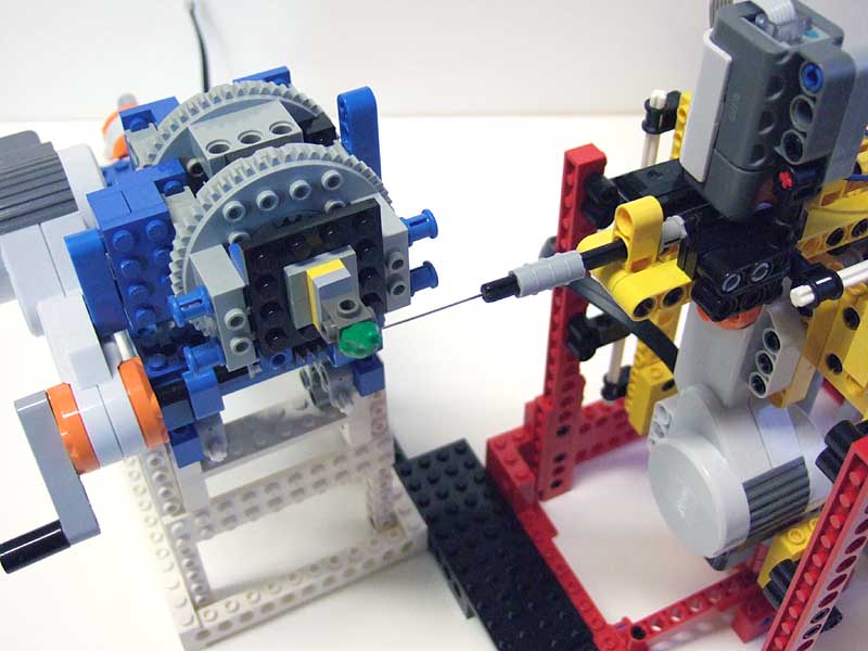
Top view, showing the probe carriage. The needle is the only non-LEGO part. It is glued in a hole drilled in a 2L axle, and must be as sharp as possible to limit slipping on the object. Take care of your fingers!!! |
|
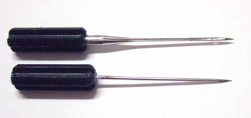
Here is a close up of the probe tips I created for this project. The bottom one used a simple pin, I then moved to the better top one, using a sewing machine needle. The stiffer steel make it more precise. |
|
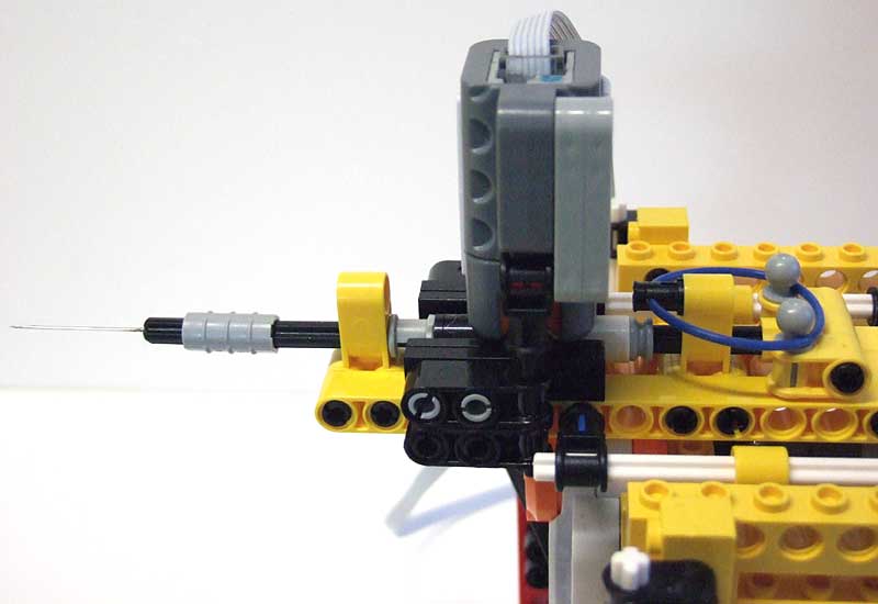
Detail of the probe. The needle is mounted on an axle that is maintained by a very slightly taught rubber band. When the needle touches the object, the axle goes back a little and a black and a white pin joiners move in front of the light sensor. This allows detection of the contact with very little force applied on the object (so the object is not punched by the needle!). Note the use of a Mindsensors Flexi-Cable to connect the light sensor. Though reasonably rigid, the needle carriage assembly bends when a regular stiff cable is used. |
|
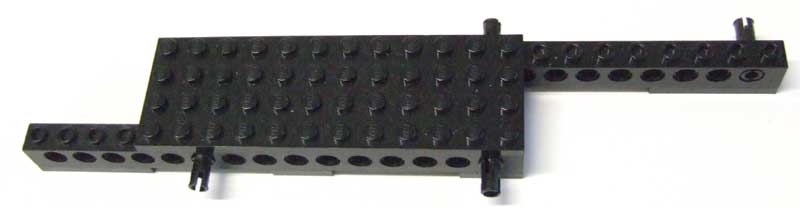
This assembly is used to attach the modules together. It can be easily modified to adapt to various sizes of scanned objects. |
|
The modules configured in polar scan setup. I have not yet written the programs needed for that kind of scan |
|
Scanning a part can be very long (several hours). To save on batteries I used my NXT supply adapter. Of course you can also use the LEGO NXT Li-ion battery with its mains adapter. |
|
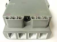
NXT ports affectation. |

Video
Miscellaneous issues
Though the results are quite convincing, a few issues remain.
Building
No building instructions (yet), but complete MLCad files here (unofficial parts included)
Programs
This project needs to return large amount of data to the PC, much larger than memory available in the NXT. So a permanent connection was needed. Since I didn't want to write code on PC side, I turned to pbLua. pbLua communicates with the host computer through a virtual serial port, either through USB or Bluetooth. Getting scan data is thus simple: NXT "prints" point coordinates to the console, and a terminal emulation software (I used TeraTerm and Putty) logs all received data to a file. Alternatively you could use pbLua newly introduced Xmodem to send data to the host computer.
Data is sent using ".obj" 3D ASCII format, consisting simply of 3D coordinate triplets preceded by letter v: v -5.000000 -8.500000 24.041666. After the scan is completed, use a text editor to clean-up the log file (remove console output before and after scan) and save it with .obj file extension.
|
Scan Setup program. Send it to pbLua console, then execute Setup() function. A menu is then displayed on NXT screen, follow it to setup all three scan boundaries, and initialize light sensor threshold. At the send of setup, all useless functions are erased from memory, making room for scan function. |
|
Scan program. Send it to pbLua console, start the log of your terminal program, then execute ScanXY(dx, dy) function. dx and dy define the scan resolution, expressed in motor ticks. 96 motor ticks = 0.4mm = 1 LDraw unit. ScanXY(48,48) perform a scan with a 0.2mm grid resolution. Scan setup MUST have been performed before scanning! |

Of course these programs can be installed in NXT flash memory (see tutorial). Warning: the scan setup program is too big to be loaded in NXT memory in one string. You have to do that in two steps (see example here).
3D reconstruction
After scanning all sides of your object, you need to transform all those long lists of coordinates into a nice 3D virtual model. MeshLab (a tool developed with the support of the Epoch NOE) is an open source, portable, and extensible system for the processing and editing of unstructured 3D triangular meshes. Here below is a walk-through of the reconstruction process. Screenshots and descriptions are based on alpha version of MeshLab 1.2 (MeshLabSetup_v120ALPHA_2009_02_08) I choose this version because it supports text version of stl format, necessary to use stl2dat LDraw converion tool. Note that I am NOT a 3D expert, and there may be easier/more efficient ways to do this.
This zip file (900kB) contains some examples
at various steps of the process.
|
Import the .obj file into MeshLab. The file contains only dots, and MeshLab accordingly sets display mode (circled in red). (sample: FrogSide.obj) |
|
We now add triangle on the dots skeleton. To do that we apply a reconstruction filter: Filters > Remeshing, simplification and reconstruction > Ball Pivoting Surface Reconstruction. Default options give good result so click "apply" and close filter window. The triangular mesh will not show till you choose an appropriate display mode (flat lines, circled in red). |
|
We now clean-up the mesh of unneeded parts, mainly background. Use the selection tool (circled in red) on the unwanted portions. In addition to background, try to remove areas where needle direction was almost tangent with the surface of the object (since the needle slips in these areas, dot coordinates are very imprecise. You may use control key to extend selection, shift key to remove from selection, esc key to toggle between selection mode and space orientation/navigation mode. Note that selection operates on all triangles under the cursor, even hidden back faces. |
|
Hitting Del key suppress all selected triangles. Note that I purposely left the 1 x 1 brick top under the frog, as it will help to assemble the various elements. Save the result in .ply format (sample: FrogSide.ply). Process all the scans of the frog (FrogTop.obj, FrogFront.obj, FrogBack.obj) to obtain the meshes (FrogTop.ply, FrogFront.ply, FrogBack.ply). Note that only half of the (symmetrical) frog were scanned to save time. |
|
We are now going to align properly all parts of the scan. Meshlab has automatic alignment functions, but they don't seem to work properly here, probably because there is little overlap between the various files. So I'll show the fully manual method. I have prepared a 3D file of a 1x1 brick (converted from LDraw using 3dto3d). It will be used to anchor the frog on top. Open the brick (brick1.ply) then frog side (FrogSide.ply) as a new layer (File > Open as new layer). Since the scans are done along cartesian direction, it is easy to rotate frog side by 90° around mains axis to get proper orientation. Launch the "Apply Transform" filter (Filters > Normal, Curvature and Orientation > Apply Transform). In the dialog that opens, check "Relative Transformation mode", "Rotate", set angle to 90° and choose rotation axis (here, Y). |
|
When you are satisfied by the result, close the "Apply Transform" window, then commit your transformations (Filters > Normal, Curvature and Orientation > Apply Transform > Freeze Current Matrix). Note that "Apply Transform" has a close and freeze button that would do both operations, but it is clumsy to use in relative mode, since it applies the transformation once more before freezing. |
|
Frog side is now correctly oriented, but not properly placed. While we also could use the "Apply Transform" move mode, it is simpler to use an interactive method, so we shall use the Alignment tool. Start the alignment tool (Yellow A icon of toolbar). Click on FrogSide in the layers list then on Manual Rough Glue button. |
|
You can now align the frog side with
the brick. Use control+mouse drag to pan (move)
the frog side. Note that if you forget to press
the control key you will rotate the layer, which
is not desired here. |
|
Now add other parts of the frog one at a time, and perform the same rotation and positioning steps (FrogBack.ply, FrogFront.ply, FrogTop.ply) on them. Don't forget to freeze matrix and save each layer as you progress (FrogBack-b.ply, FrogFront-b.ply, FrogTop-b.ply). Use the layers dialog ("stack of sheets" icon) to keep track of where you are. Note that you can save only one layer at a time. Half of the frog is now ready... |
|
The brick is no longer needed, select it in the layer dialog and press the "-" button. We will now merge all layers in a single one: Filters > Layer management > Flatten visible layers. Then save the result (frog-half.ply) |
|
Now we need the other half of the frog, created by mirroring . Apply a symmetry: Filters > Normal, Curvature and Orientation > Apply Transform. A dialog opens, check "Relative Transformation mode", "Scale" and set X scale value to -1, then click on "Close and Freeze" button. The second side of the frog is now ready, but it appears dark... This is because the symmetry operation didn't change facet orientation. To correct that, use Filters > Normal, Curvature and Orientation > Invert Faces Orientation. Then save the result (frog-half-sym.ply). |
|
Reopen the first frog half in a new layer, flatten the result (Filters > Layer management > Flatten visible layers), then select and suppress the scanned top of the support brick. Make sure to use the "Delete faces and surrounding vertices" button (circled icon). Save the result (frog-raw.ply) |
|
The raw frog is not build from a single sheet of triangles, we need to create a new shape from the raw version with a Poisson reconstruction (Filters > Remeshing, simplification and reconstruction > Poisson reconstruction). This creates a new layer. Hide the raw layer by clicking on the eye icon in layers dialog, and admire the result! As you can see, this reconstruction also filtered out scanning noise (frog-final.ply). As there is a very good utility (stl2dat) to convert SolidWorks format to LDraw format, we will save the result this way as frog-final.stl. Remember to uncheck "binary encoding", stl2dat manages only text format. |
The LDraw file I submitted to LDraw parts tracker was done from there: |
|


|
Another scanned part. |
![]()
![]()
![]()
![]()
![]()
![]()
![]()
![]()
![]()
![]()
![]()
![]()
![]()
![]()
![]()