![]()
![]()
![]()
![]()

![]()
![]()
![]()
![]()
![]()
![]()
![]()
![]()
![]()
![]()
![]()
- V1.0: Initial release
- V1.1 (sept 2009): Corrected a bug preventing inlining of subparts in current folder when used with LETGUI
- V1.2 (april 2010): Corrected a bug that prevented creation on a line for some angles. Added -b option.
- V1.3 (sept 2010): Now creates conditional lines on top of existing ones (in primitives) if needed. Flat angle default is now 0.1° instead of 1°.
- V1.4 (feb 2014): When inlining, color was not properly transmitted to child elements.
- The input file may contain any LDraw type. Primitives and subfiles are ignored unless Edger2 is told to inline them.
- Launch a command prompt
- Type the command line: Edger2 [options] Infile, Outfile. Edger2 will create Outfile containing the newly created lines appended to Infile data (this behavior may be changed with command line switches described below. Note that if file LdrawCutFileOut exists it will be overwritten without warning.
- Input file is parsed, and its content is stored into an array. If a -d option is present, conditional lines (-dc) or edge lines (-de) are deleted and are not stored in the array.
- If the user selected a subfile (-s or -i options), the array is scanned and all subfiles/primitives that are found in defined LDraw path (-l option) are inlined at the end of the array. This inlining is done in a BFC compliant way.
- We then look for unmatched edges. For each side of triangle/quads, the array is scanned to see if another element (triangle/quad/edge line/conditional line) share a common side. If none is found, an unmatched edge line is added at the end of the array. This line is colored in red for easy spotting, as un unmatched edge should not normally occur in a part. Note that side comparison is done with some error margin (-p option) to ensure that rounding errors that occur during part creation are accounted for.
- We then scan the array again, this time to find common
vertices between triangles/quads. When one is found, we
compare the angle a between adjacent elements and
the threshold angles specified with -af, -ac and -ae angles.
- if a < af, the angle is very flat and no line is created.
- if af < a < ac, the angle is shallow and a conditional line is created.
- if ac < a < ae, the angle is neither really shallow nor really sharp. Overlapping conditional line AND edge lines are created. These lines are created in green color to attract user attention: one of these lines must be manually deleted.
- if ae < a, the angle is sharp and an edge line is created.
- Note that angle a is kept in range 0..90° if -b option is not specified. With -b the full range 0..180° is used, but this requires a BFC valid part.
- Note that in the above step, if a -cx or -cv option is specified, conditional lines are created only if surface junction is convex (-cx) or concave (-cv).
- Output file is written. Depending on -i option, either the original form is written, or an expanded version with primitives/subfiles inlined is created.
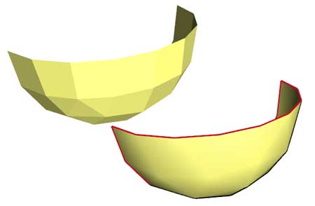
- the input file, that might be a section of tire.
- Result of Edger2 with default options. We see that the outside edge of the shape is now outlined with red edge lines (unmatched sides), and the sharp angles have an edge line.
- Same file, but this time LDView is set to display conditional lines. We see that Edger2 has also added conditional lines on all shallow angle quad junctions.
- Here we used -c option. Used to check the work of Edger2, this option colors newly added edge lines in pink, and conditional lines in light blue.
|
Edger 2,
a LDraw line adder tool
Lee Gaiteri's Edger utility allows to create conditional lines between adjacent facets, and edge lines on outside (unmatched) facets. But it has a few drawbacks, such as requiring perfect match between facets (something hard to get because of limited precision of some tools such as MLCad), and it doesn't manage subparts or primitives. Since we had a C++ training at job, I suggested to write an improved version of Edger as an application exercise. Edger2 is the result...
It is a simple console application, source code is provided below to anyone willing to integrate it in a more palatable user interface. You may also use Michael Heidemann LETGUI front-end (highly recommended!).
Download
Edger2 package, including program for Windows, documentation, source files (Visual C++ 6.0), sample files.

History
Usage
Here is a screen shot of a sample run:
How Edger2 works
Examples
|
|
From left to right: Command line: edger2 edg1.dat edg1o1.dat edger2 -c edg1.dat edg1o2.dat |
|
|
Here we see the role of precision. -p option controls the maximum distance between two points that Edger2 will consider matching. The piece of this example was built by duplication and rotation of one section. Because of rounding errors while doing the rotations (MLCad has limited precision, LDDP is only slightly better), points of adjacent facets don't have exactly the same coordinates. If specified precision is too high, they are too far away to be considered matching and red non-matching lines are created. Default value for precision is 0.001. Command line: edger2 -p 0.0001 edg1.dat edg1p1.dat |
|
-af parameter specifies the angle between facets that is flat enough not to need a conditional lines. On the example shown, -af is set ot 0, and Edger2 needlessly inserts conditional lines on the flat sides. Default value is -af 1 (1°). Command line: edger2 -c -af 0 edg1.dat edg1a1.dat |
|
-ae parameter specifies the angle above wich Edger2 creates normal edge lines. Here we set -ae to 20°, so sections junction (that have an angle of about 30°) receive edge lines instead of conditional ones. Default value for -ae is 60° Command line: edger2 -c -ae 20 edg1.dat edg1a2.dat |
|
-ac parameter specifies the maximum angle below wich Edger2 creates conditional lines. Here we set -ac to 20°, so sections junction (that have an angle of about 30°) are in the "no mans land" between conditional lines and edge lines. They get both an edge line AND a conditional line. They are both colored in green for easy spotting: the user will have to manually suppress one of them. In the resulting LDraw file, the edge line is followed by the conditional line. This mode is useful to fine tune 3D files such as LDraw files received from LEGO Universe Team (see here for more details). Command line: edger2 -c -ac 20 edg1.dat edg1a3.dat |
|
|
Unmatched edge line behavior is controlled with -u parameter. With -u+ create only unmatched edges. This option is useful to create the edge line that will be used for example with Coverer or Ytruder (See also the usage for T-junction detection at the bottom of this page). When you don't need these unmatched lines, use -u-. Note that you may use -u- and -u+ at the same time: in this case Edger2 created no new lines! We will see below the usage of this possibility. Command line: Edger2 -u+ -c edg1.dat edg1u1.dat Edger2 -u- -c edg1.dat edg1u2.dat |
|
|
|
We can restrict creation of conditional
lines to convex surfaces using command switch -cx,
or to concave surfaces (-cv). Technically conditional
lines are only needed on convex surfaces, but since
LDview smoother needs condlines everywhere to do
its wonderful job, I don't know if this option will
have much use. Of course, Edger2 needs to know inside
from outside to know if the surface is convex or
concave, so a BFCed input file is needed. -cv option
creates conditional lines only on concave surfaces.
Added for the sake of completeness, but should be
even more useless! The last example shows the need for a file that has correct orientation for all facets: despite convex option, conditional lines were added on the wrongly oriented concave section. Command line: Edger2 -cx -c edg2.dat edg2cx.dat Edger2 -cv -c edg2.dat edg2cv.dat Edger2 -cx -c edg2a.dat edg2cxbad.dat |
|
|
|
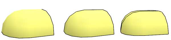
(new in version 1.2) Since molded parts rarely have sharp edges, Edger2 default behavior is to assume that angle between facets normals is between 0 and 90°. This has the benefit that it works correctly even if the part is a patchwork of direct and inverted BFC elements. But sometimes it is useful to be able to manage sharp angles correctly. In the above example, Edger2 will set conditional lines instead of edge lines on triangle corners, especially if condline/edgeline threshold is set high. With -b option, angle between normals is evaluated in 0..180° range, but this requires a BFC valid file to work Command line: Edger2 -ac 70 edgebin.dat edgenob.dat Edger2 -ac 70 -b edgebin.dat edgeb.dat |
|
|
-w instructs Edger2 to save only newly created lines. This behavior is similar to Edger. Command line: Edger2 -w -c edg1.dat edg1w.dat |
|
|
-dc and -de options allow to delete existing lines before regenerating them. Note that in case of subfiles this only affects the main file, not the subfiles or primitives, even if -s or -i option are specified (see below). Command line: Edger2 -dc -de -ac 30 -ae 50 LUT2543.dat edg3d.dat |
|
|
|
Subfile expansion is one important improvement of Edger2 on Edger. By default Edger2 only looks for missing lines in the main file, but with this option it will look also in the subfiles/primitives. Of course this is mainly useful at the mainfile/primitives boundary, or to create condlines at the junction between subfiles. This is the case in the example shown, the four sections forming this wheel receive conditional lines where they meet. By default, subparts are only searched in input file folder and relative \s and \p folders. Command line: Edger2 -s edg4.dat edg4s.dat |
|
|
|
If you want to look also into primitives, you need to specify your LDraw path. This is done with the -l option. In addition to input file folder, Edger2 searches for specified paths. When -l "ldp" is specified, it searches ldp\p\, ldp\parts\, ldp\parts\s\, ldp\Unofficial\p\, ldp\Unofficial\p\parts\, ldp\Unofficial\p\parts\s\. You may have several -l parameters, adding new search paths. The example above shows a shape formed by stacked cylinder and cones primitives, Edger2 adds conditional lines at the junction. The third image show the nice smoothing resulting. Command line: Edger2 -s -l c:\ldraw edg5.dat edg5l.dat |
|
|
|
(new in version 1.3) Primitives such as partial cylinders or spheres have conditional lines on edge. For cylinders, these integrated conditional lines are expected to match a tangent plane, for spheres they match a joining cylinder. If you try to join something directed inwards, integrated conditional lines will not show properly while they should (left image). Edger2 properly creates an overlapping conditional line in that case (middle image). Note that unfortunately nothing will prevent the conditional line to appear at the wrong incidence if you try to join something directed outwards (third image, file edg6b). Edger2 can't do anything there. Note that cylinders properly matches other cylinders (and spheres matches spheres) because conditional lines on each side complete each other properly. Command line: Edger2 -s -l c:\ldraw edg6.dat edg6a.dat |
|
- -i+: expand subfiles and output inlined data with subfile comments.
- -i-: expand subfiles and output inlined data without subfile comments.
Edger2 as an inliner
With the adding of subfile capability (included BFC management needed for convex/concave options), I had the engine of a BFC-aware inliner. So I added -i option to write this inline data in the output file instead of subfile references.
These options both output inlined primitives and subfiles.
The second also suppress any comments present in the subfiles.
Use together with both -u- and -u+ options (this prevents Edger2 to add any new line). The following command inlines the cones from previous example:
Command line: Edger2 -u- -u+ -i- -l c:\ldraw edg5l.dat edg5linl.dat
Edger2 as a
T-junction and gap checker
|
T-junctions should be avoided as they can cause artifact in part display (about T-junctions, see this Lugnet thread). The example above show a pattern with many T-junctions and a teeny gap on left side. Using the unmatched side detection of Edger2 clearly show these problems as red lines in the middle of the pattern. Command line: Edger2 -u+ -s -l c:\ldraw tjunc.dat tjunco.dat |
|
Viewing the result in wireframe mode show the failure modes:
|

![]()
![]()
![]()
![]()
![]()
![]()
![]()
![]()
![]()
![]()
![]()
![]()
![]()
![]()
![]()