![]()
![]()
![]()
![]()

![]()
![]()
![]()
![]()
![]()
![]()
![]()
![]()
![]()
![]()
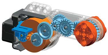
NXT® motor internals
|
Image provided by LEGO education |
February 2007 update: Ryo Watanabe computed NXT motor constants from the curves below, as well as from his own measurements. Read more here.
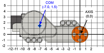
March 2008 update: Kevin Knuth of BrickEngineer experimentally determined the center of mass of NXT motor.
November 2008 update: Daniele Benedettelli sent me photos of a fully open broken NXT motor. See bottom of this page.
December 2020 update: RocGravillon sent me photos and procedure to properly open NXT motor without breaking hub. See here.
NXT motor characteristics
9V motors comparison page shows some characteristics of this motor considered as a 9V motor, but here are some more information on its use with a NXT (its main use!!!)
The curves below shows NXT motor rotation speed (Rotations per Minute) vs. motor power level (supply duty cycle).
|
|
|
|
|
|
|
|
|
The following charts show the characteristics of the NXT motor versus applied load. For the dark blue curves, the NXT was powered at 9V (voltage of alkaline batteries), the magenta ones were obtained at 7.2V (voltage of NiMH batteries). Power level is 100% for all charts.
This curve shows that the maximum mechanical power is obtained at a torque load of about 15 N.cm. If you compare to the curves obtained for the RCX with 71427 motor, you see that the available mechanical power is much higher, almost 4 times! Even powered with 7.2V NiMH batteries, the NXT can deliver more power than a RCX output with 2 paralleled motors and 9V supply. This comes with a price of course, the current drained at that power level is much higher - you better have good batteries...
The current vs. torque shows a linear increase with the load. Because of power limitations in NXT driver, and thermistor trip current in NXT motor, I suggest that you don't exceed a 15 N.cm torque for extended time periods. Higher loads (thus current drains) are possible for short periods, but the protections will soon reduce current and available power.
Photo Gallery
The cool drawing at the top of this page shows
many things, but nothing beats seeing the real thing. So I opened
one of my motors and took some photographs...
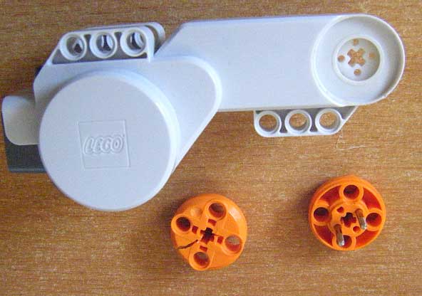
Warning: Separating the orange shaft
parts is impossible without breaking things. Don't try that!
Also notice that reassembling the motor partially opened as
I did can be tricky!
|
Once you have removed all seven screws visible outside (using a thin Torx T5 screwdriver), there is an eighth one to be removed inside... You can access it by flexing the plastic motor case. |
|
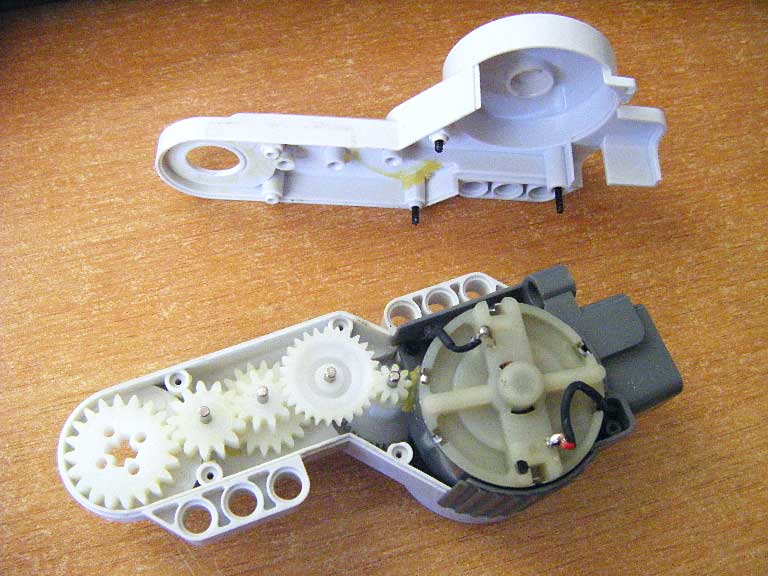
When all screws are removed, you can slide the motor assembly out of its case. |
|
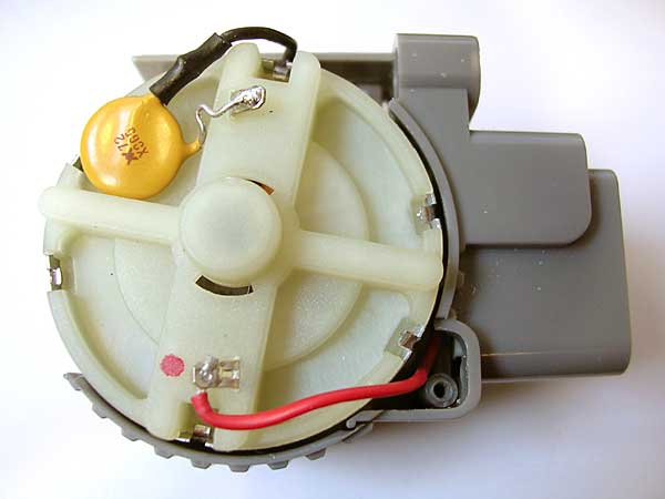
The yellow component is a resettable fuse that protects the motor and the NXT from over-currents. It's a Raychem RXE065 or Bourns MF-R065. |
|
The other side of the motor shows the encoder wheel and optical fork that provide rotation sensor function to the NXT motor. |
|
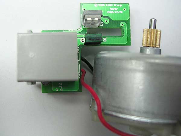
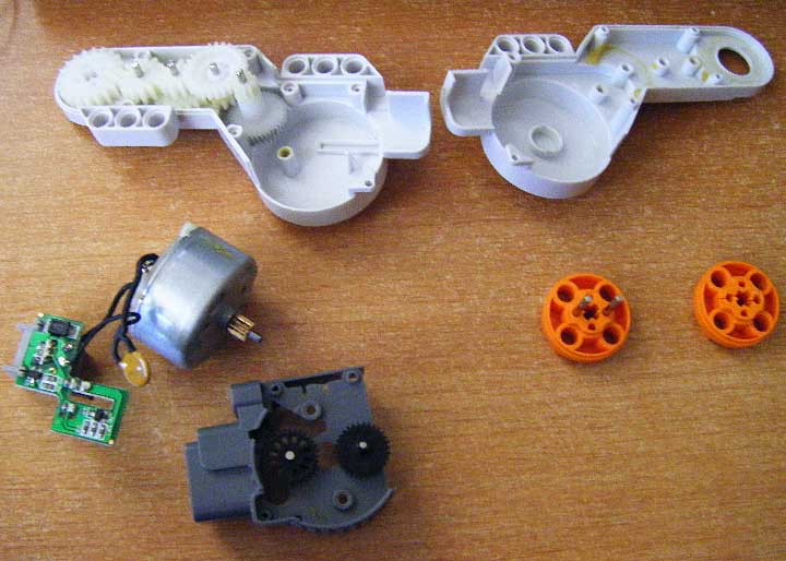
The motor and printed circuit board bearing motor connector and optical encoder. |
|
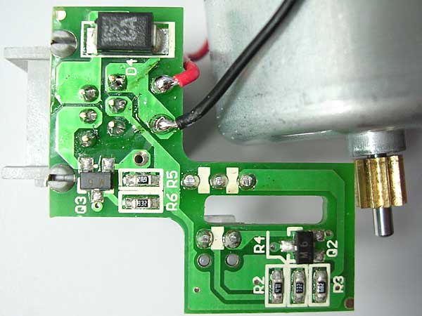
Bottom of the PCB, mainly used for optical encoder signal conditioning. The black rectangular component on top is a surge suppressor that clamps voltages to 15 volts maximum. |
|
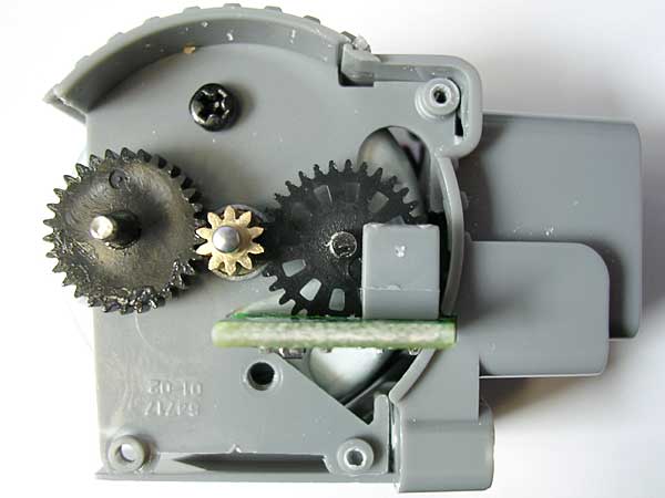
You may also have a glimpse on the gear train. Unfortunately, since the orange shaft parts can't be separated, we can't go further. |


Here below are some photos of a broken NXT motor, fully open. Photos courtesy of Daniele Benedettelli.
|
Output shaft of the motor broke under load! This photo also shows the asymmetric ribs on the metal pins explaining why it is impossible to disassemble the hub without breaking it. |
|
Motor hub and casing. |
|
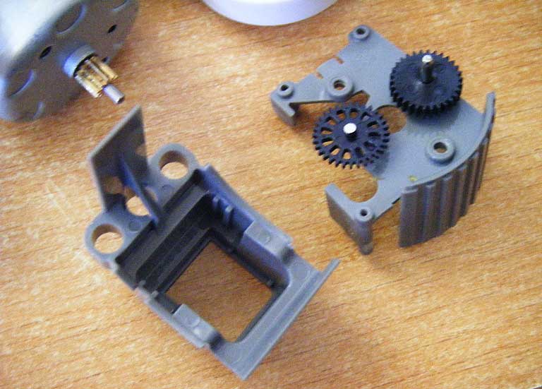
Photo showing motor inside. |
|
Close-up on the gear train. From motor to output shaft, we get these gear ratio: 10:30:40 = 1:4
9:27 = 1:3
10:20 = 1:2
10:13:20 = 1:2
Overall 1:48 |
|
Encoder wheel and enclosure back parts. We have 12 slits in encoder, and motor to encoder gear reduction is 10:32. So for 1 turn of output hub, encoders turns 48*10/32=15 turns, optical detectors sees 15*12=180 slits. Using both sides of slits gives nominal 360 ticks per turn resolution. Note that since we have a quadrature encoder, the maximum resolution is 720 ticks/turn, but this is not used by standard NXT firmware. |
|
Exploded view of the motor. |


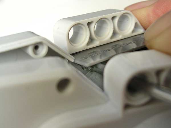
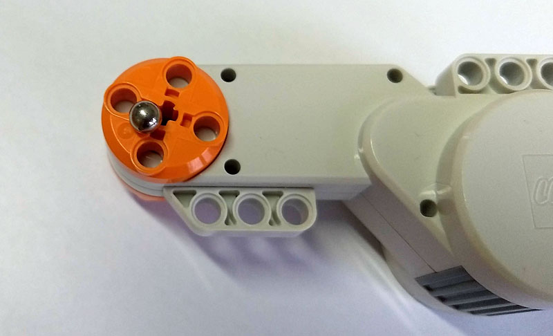
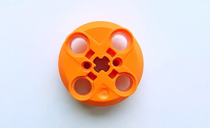
- A small magnet is used to precisely locate where the metallic pins are located
- Drill 3 mm holes in hub plastic at these places until you reach the metal pins
- Do this on both sides
- Using a 1.9mm bit and a mallet, carefully push the metal pins until you are able to separate the halves of the hub.
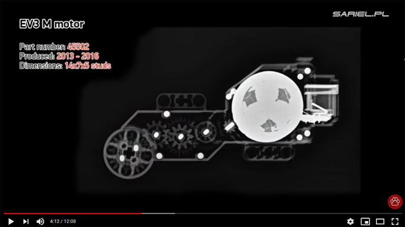
- This method should work also with EV3 motors. On this screenshot extracted from Sariel's video, we see the metallic pins in the hub. Unfortunately, they don't seem to be magnetic so the magnet trick to locate them doesn't work.
RocGravillon sent me photos and procedure to properly open NXT motor without breaking hub.
|
|
|
|
|
|
|

![]()
![]()
![]()
![]()
![]()
![]()
![]()
![]()
![]()
![]()
![]()
![]()
![]()
![]()