![]()
![]()
![]()
![]()

![]()
![]()
![]()
![]()
![]()
![]()
![]()
![]()
![]()
![]()
![]()
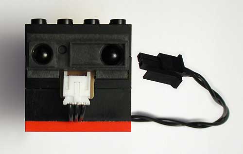
GP2D12 distance sensor
|
|

I long thought that a distance sensor would be a nice addition to Mindstorms robots, but ultrasonic ones were bulky and power hungry (I've since found Robot Electronics Ultrasonic Range Finder that can perhaps be used), and simple infrared method like the one I used in my radar car detects obstacles but don't give true distance measurement. The solution came from Andreas Peter (thanks Andreas for showing me these devices !) who interfaced a Sharp GP2D02 to RCX.
These small and rather inexpensive infrared devices are able to measure distance between 10 and 80 cm with reasonable precision and good immunity to variations of obstacles reflectivity and ambient light. For more informations, read GP2D12 datasheet and Acroname article: Demystifying the Sharp IR Detectors.
Andreas sensor interface has a few drawbacks though. The GP2D02 he could find has a digital serial output not well suited to RCX analog input, thus requiring a rather complex design, big and power hungry.
So I decided to try to connect the analog output GP2D12 sensor
using the simplest design possible - and use only power coming
from sensor input. This was a real challenge since GP2D12 used
35 mA under 5 V, while RCX sensor input is current limited to
about 14 mA ! (look at voltage versus current of sensor input
power supply:  ).
).
The main concept to achieve this goal was quickly imagined: store energy in a capacitor while GP2D12 is not powered, then release it during measure. Of course there is a penalty with this technique: conversion time is longer. GP2D12 requires 50 ms per measure, while my circuit needs 300 ms... there is no free lunch!
The first designs I imagined were rather complex, with timers and sample-and-hold amplifier, then I slowly came to this streamlined circuit:
Circuit working
Charging phase:
During
250 ms, sensor is configured as a light sensor (powered), C1
charges through D1 up to SENSOR+ voltage. Low drop regulator
U1 generates a 5V regulated supply. Q1 is blocked by D2 (D2
maintains base to a voltage higher or equal to its emitter voltage),
so GP2D12 is not powered. Q3 is non-conducting too, preventing
current flow through D3/R5/Q2. So the only significant current
diverted from C1 charging is through R1 (less than 2 mA), and
at the end of this phase C1 is fully charged.
Measure phase:
During
the following 50 ms, sensor is configured as a touch sensor
(passive). SENSOR+ is now only pulled up to +5V through 10Kohm
(inside RCX), insufficient to block Q1. Q1 and Q3 are then conducting,
and GP2D12 is powered. Q2, mounted as an emitter follower, buffers
GP2D12 output and its value is available to RCX through D3 and
R5.
Sample code to read sensor:
SetSensor(SENSOR_1,SENSOR_LIGHT);

Wait(25);

SetSensor(SENSOR_1,SENSOR_TOUCH);

Wait(5);

SetSensorMode(SENSOR_1,SENSOR_MODE_RAW);

distance=SENSOR_1;

SetSensor(SENSOR_1,SENSOR_LIGHT); //Enable C1 charge as soon as possible
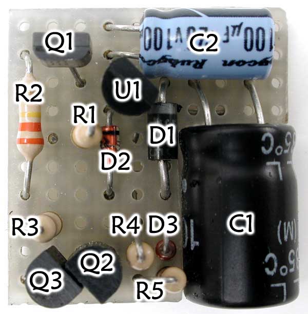
Component selection
- D1 prevents destroying the sensor in case of reverse connexion. I didn't use the full bridge rectifier used in Lego sensor that enables sensors to work when connected backwards (number of needed diodes jumps from 3 to 8 !). I considered that someone able to build this sensor is also able to connect it in the right way... For those who want it, here is the diagram with full bridge rectifier.
I used 1 Amp. Shottky diode 1N5819 for D1, inexpensive and readily available. Its low forward drop foltage is less than 0.1V for the current that flow through it, this enables to charge C1 to the highest voltage possible. - C1 stores energy that will be used during measure phase, it must provide 5V at the end of this stage. Assuming typical values for GP2D12 (I=35mA, conversion time=50ms) and an initial 7.5V across C1, its value is C = I * dT / dV = 35 * 50 / (7.5-5) = 700 µF. Small margin with 1000 µF...
- U1 is a low drop out 5V regulator in TO92 case. I used a Telcom/Microchip TC55RP5000, but other regulators will probably work, such as STMicroelectronics L4931-50. Standard regulators such as 78L05 will NOT work because they require more than 7V at input to get a 5V output. Take care with some low drop regulators such as LM2931 that require more than 25 mA when powered at 1V. With RCX current limitation, this hog eats all energy. (I was caught with this one...)
- Q1 switches power on and off for GP2D12. At 35 mA current, I originally used a plain-vanilla BC548. My sensor began to work with it, but exhibited strange behavior. Looking to GP2D12 power supply I then discovered 2V dips ! I then looked at GP2D12 consumption and discovered that it was pulsed (220mA pulses 1/8th of time, supperposed to a 8mA constant current. See oscilloscope captures here). At such a current, BC548 has a low gain, and since I couldn't lower base resistor R1 (main current drain during capacitor charge) I used a high performance Zetex transistor, ZTX718 that offers high gain at high current (other similar devices can work!).
- C2 stabilizes U1 and helps absorb peaks of current. A low ESR version would be better (see "grass" on 5V output when GP2D12 works).
Main components datasheets (.pdf documents)
Where to buy GP2D12 ?
GP2D12 can be bought from Acroname (Part Number: R48-IR12) or from Conrad (Part Number: 0185309)
Oscilloscope screen captures
See them here. 
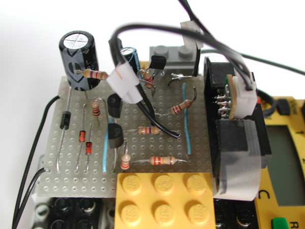
Building sensor interface module: photo gallery
|
|
|
|
|
|
|
|
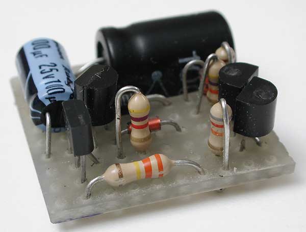
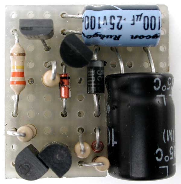
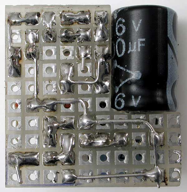
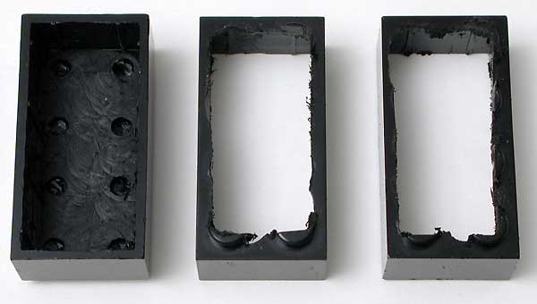
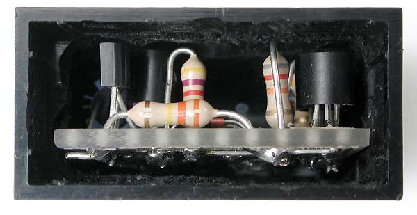
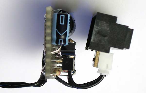
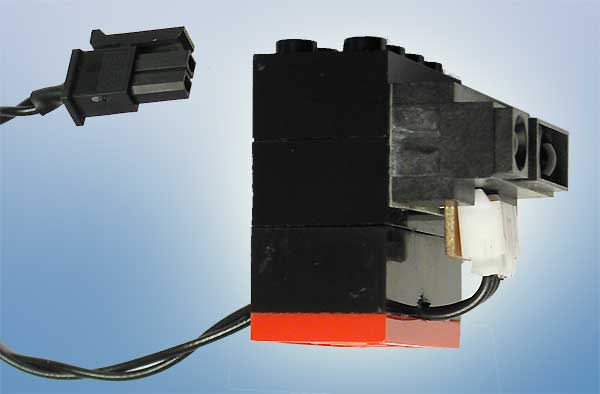
The prototype...
|
|
|
|
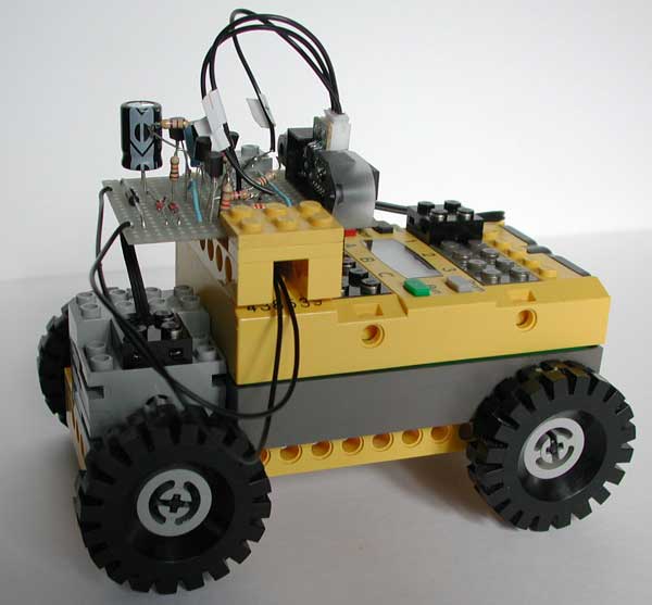
A real application: a wall follower
See it here !
Test programs
![]() test programs (requires
RCX 2.0 firmware that you can get here)
test programs (requires
RCX 2.0 firmware that you can get here)
- testGP2D12.nqc reads GP2D12 sensor output and displays raw value on RCX display.
- measure.nqc reads GP2D12 sensor output and displays distance (in cm) on RCX display. Value read is proportionnal to inverse of distance with some offset (see above old GP2D12 documentation), you can find here the Excel sheet I used to find the equation converting raw values to centimeters.
|
|
![]()
![]()
![]()
![]()
![]()
![]()
![]()
![]()
![]()
![]()
![]()
![]()
![]()
![]()
![]()