![]()
![]()
![]()
![]()

![]()
![]()
![]()
![]()
![]()
![]()
![]()
![]()
![]()
![]()
![]()
- V1.1: Initial release
- Prepare the input LDraw pattern file. Pattern file may contain lines, triangles and quads, as well as flat primitives (see details below). Other LDraw line types are ignored.
- The 3D former file only deals with triangle and quads. Primitives may be inlined using -sf command line switch. Other LDraw line types are ignored.
- Launch a command prompt
- Type the command line: Slicerpro [options] LdrawPatternFile Ldraw3DFile Ldraw3DPatternFileOut. SlicerPro will create Ldraw3DPatternFileOut, containing the raised pattern surface. Note that if file Ldraw3DPatternFileOut exists it will be overwritten without warning.
- SlicerPro outputs file with 6 digits after decimal point, this precision is excessive for most usages and values should be rounded. LDDesignPad or DatHeader does that very well.
- -x: Pattern and former in y-z plane, projection in x direction
- -y: Pattern and former in x-z plane, projection in y direction (default)
- -z: Pattern and former in x-y plane, projection in z direction
- -n: No projection, only slicing
- -c: Copy conditional lines from former file to output
- -t: Don't retriangulate (debugging)
- -m: Merge polys of uniform color facets
- -ui: Don't unify vertices in input files
- -uo: Don't unify vertices in output file
- -ut <val>: Vertices unification threshold (default 0.005)
- -sp: Expand subfiles in pattern
- -sf: Expand subfiles in former
- -l "path": define ldraw search path
- -p <val>: precision (default 0.001)
- 3D former file is read and parsed. If -sf is specified, subfiles are recursively inlined. All surfaces are stored in an array.
- Pattern file is read and parsed. If -sp is specified, subfiles are recursively inlined. All elements are stored in an array.
- Vertices of elements in both arrays are "unified". To do so, points very close to each other are replaced by their center of mass. "Very close" means their distance is lower than threshold defined by -ut parameter, 0.005 is the default value. This helps to close small gaps existing in the part because of rounding errors. It is possible do disable this step using -ui option.
- If -x or -z options are specified, pattern and former arrays are re-oriented
- A copy of the former array is done to keep 3D information.
- Pattern and former arrays elements are flattened, and their winding is unified.
- Former array is then processed one surface at a time.
- For each former surface, overlapping elements from the pattern are selected.
- The pattern elements (except subfiles!) are cut along the edges of the surface.
- The surface cutting process may provide more pieces than needed. We get the convex hull of these elements (since the intersection of two convex shape is convex) and re-triangulate it to get an optimum number of elements. Note that this re-triangulation may be disabled with -t parameter.
- Unless -n is specified, all these elements are projected on the 3D former. For each apex of lines/triangles/quads, y coordinate of the 3D former at (x,z) point is calculated. (x,y,z) is then the 3D coordinate of the resulting apex. For primitives, projection of the primitive origin is calculated. Orientation of the 3D file facet that contains the projected origin is then used to construct the transformation matrix of the projected primitive. This is meaningful only for flat primitives that extend in x-z plane. It is the case of all disc, ndisc and ring primitives. Again, non-inlined primitives are not cut, so they must project completely on one former element or weird results will occur.
- Vertices of elements in output are "unified". This can be disabled with -uo parameter.
- Output file is written.
- the pattern file, a nice color patchwork, extending in X-Z plane.
- a cone, made from triangles (inlined version of hires cone0 primitive), also mainly extending in X-Z plane
- Patterned cone created with SlicerPro
|
SlicerPro, a LDraw slicing and stamping tool
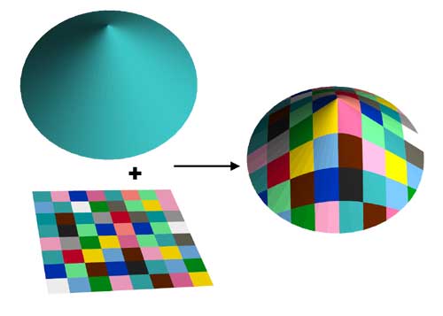
SlicerPro utility allows to stamp a flat pattern over a 3D former. Each set is provided to the utility as separate LDraw files. A third file containing the raised pattern is created. SlicerPro is not a professional version of some Slicer tool, but a much improved version of my older Projector tool!
It is a simple console application, source code is provided below to anyone willing to integrate it in a more palatable user interface. You may also use Michael Heidemann LETGUI front-end (highly recommended!).
Download
SlicerPro package, including program for Windows, documentation, source files (Visual C++ 6.0), sample files.

History
Usage
Here is a screen shot of a sample run:
List of options
How SlicerPro works
Examples
|
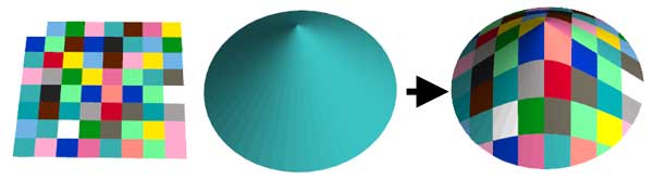
From left to right: This is the simplest case, no options are needed. Command line: Slicerpro patchworky.dat cone.dat conepat.dat |
|
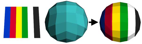
You don't need to inline things before using SlicerPro. Here the half sphere is an enlarged 4-8sphe primitive that will be inlined using -sf (expand subfiles in former). When inlining primitives, you need to specify your LDraw path with the -l option. Note that here the pattern and half sphere lie in X-Y plane, so we need to project in the Z direction (-z option) Command line: Slicerpro -z -sf -l "c:\ldraw" stripesz.dat hsphere.dat hspherepat.dat |
|
SlicerPro also takes care of BFC for you. Here the pattern and the former have mixed BCF orientation, but the result is homogeneous (depending on your need you may have to globally invert winding). Depending on projection direction, result is BFC CCW when seen from right (-x), top (-y) or front (-z). Command line: Slicerpro -z stripesz.dat hspherebfc.dat bfc.dat |
|
Pattern may extend outside the former, it will be trimmed automatically by SlicerPro. Note the use of -sp parameter to inline primitives used in the pattern. Command line: Slicerpro -l "c:\ldraw" -sp -z eye.dat 3DZ.dat eye1.dat |
|
But if you look closely at previous images, you see that a tiny gap exist around the eyebrow where regular quads meet primitives. The guy who did this pattern (me!) was too lazy to correctly calculate the coordiantes... This of course appears in the result (middle image). Fortunately the vertices unification feature of SlicerPro can be used to correct that (right image). If you increase the unification threshold (-ut 0.2), all points separated by a smaller distance will be merged together, effectively closing the gaps. Note the usage of -uo switch to prevent vertices unification to occur on output files: since some points may move a bit, some quads might not remain flat. Alternatively, the pattern could be projected on a big quad with high unification threshold value, then the resulting pattern be projected on the former. Command line: Slicerpro -l "c:\ldraw" -sp -z -ut 0.2 -uo eye.dat 3DZ.dat eyecorr.dat |
|
When you look at the previous result using LDView random colors option, you see that may elements are cut (along pattern edges) despite they are of uniform color (left image). With -m option, elements of the former that are covered by a uniform color are reported as-is in the output file (right image). The only drawback of the method is the creation of T-junctions. Command line: Slicerpro -l "c:\ldraw" -sp -z -ut 0.2 -uo -m eye.dat 3DZ.dat eyem.dat |
Sometimes the pattern edges are very close to former ones... when this occur, very tiny elements, warped quads or colinear vertices can be created. Command line: Slicerpro -l "c:\ldraw" -sp -z target.dat 3DZ.dat targetbad.dat The -p (precision) parameter can help. Reducing precision (increasing -p value) will help, because intersection computed during slicing will "snap" with a bigger radius to the former vertices. Of course you can't reduce precision too much because fine patterns would be damaged. Command line: Slicerpro -l "c:\ldraw" -sp -z -p 0.01 target.dat 3DZ.dat targetok.dat |
|
While lines are not used in patterns, SlicerPro also manages them. In this sample we apply a circle on a cylinder to obtained a saddle shaped line. This line could then be used with Coverer or PathTruder to build surfaces on it. Note that this is an application where Projector may be better than SlicerPro: Since it doesn't cut things, you distort the line without introducing many new segments. Command line: Slicerpro -l "c:\ldraw" -sp -sf edge.dat cylinder.dat saddle.dat |
|
A real part example: LDraw parts author Arezey used a preliminary version of SlicerPro to create the pattern of the Technic Sprocket Wheel 25.4 with Bionicle Life Counter Pattern (57520p01), files courtesy of Arezey. Command line: Slicerpro -sp lfc\cntpat.dat lfc\cntform.dat lfc\counter.dat (files in lfc subfolder) |


![]()
![]()
![]()
![]()
![]()
![]()
![]()
![]()
![]()
![]()
![]()
![]()
![]()
![]()
![]()